Fuel cell with passive water balance

a fuel cell and water balance technology, applied in the field of fuel cells, can solve the problems of complex manufacturing effort and cost, especially difficult to achieve water balance requirements for fuel cells used in transportation vehicles, etc., and achieve the effect of minimizing the quantity of fuel cell water and minimizing the need for active circulation

Active Publication Date: 2005-06-30
AUDI AG
View PDF9 Cites 2 Cited by
  • Summary
  • Abstract
  • Description
  • Claims
  • Application Information

AI Technical Summary

Benefits of technology

[0008] Because the first reactant flow field defines a plurality of two-pass circuits, an effective distance is significantly reduced between a reactant outlet and a reactant inlet. Consequently, the condensed water that moves from the saturated reactant stream near the outlet into adjacent porous support layers is able to readily “wick” or move by capillary action through open pores into the nearby porous support layers adjacent the reactant stream inlet. By thus facilitating passive movement of the water from a condensation zone adjacent the reactant outlet into an evaporation zone adjacent the reactant inlet, in preferred embodiments of the invention, it is not necessary to define water channels to actively circulate water from the condensation zone to the evaporation zone. Consequently, by the improved design of the reactant flow field, the fuel cell achieves a passive water balance. By minimizing a need for active circulation of a water stream and / or fuel cell water, a total volume of fuel cell water during operation is reduced which facilitates operation of the fuel cell in ambient temperatures below the freezing temperature of water.
[0010] It is a more specific purpose to provide a fuel cell with passive water balance that minimizes a need for active circulation of fuel cell water, and that minimizes a quantity of fuel cell water within the fuel cell.

Problems solved by technology

Such water balance requirements are especially difficult to accomplish for fuel cells used in transportation vehicles wherein ambient temperatures vary from well-below the freezing temperature of water to over forty degrees centigrade (“40° C.”)
Such solutions, however, involve considerable parasitic power to actively circulate a coolant stream; involve care in minimizing freeze-related problems of the coolant stream and fuel cell water; impose enhanced weight and volume requirements for the fuel cell power plant; and, require elaborate manufacturing effort and cost.

Method used


Image

  • Fuel cell with passive water balance
  • Fuel cell with passive water balance
  • Fuel cell with passive water balance

Examples


Embodiment Construction

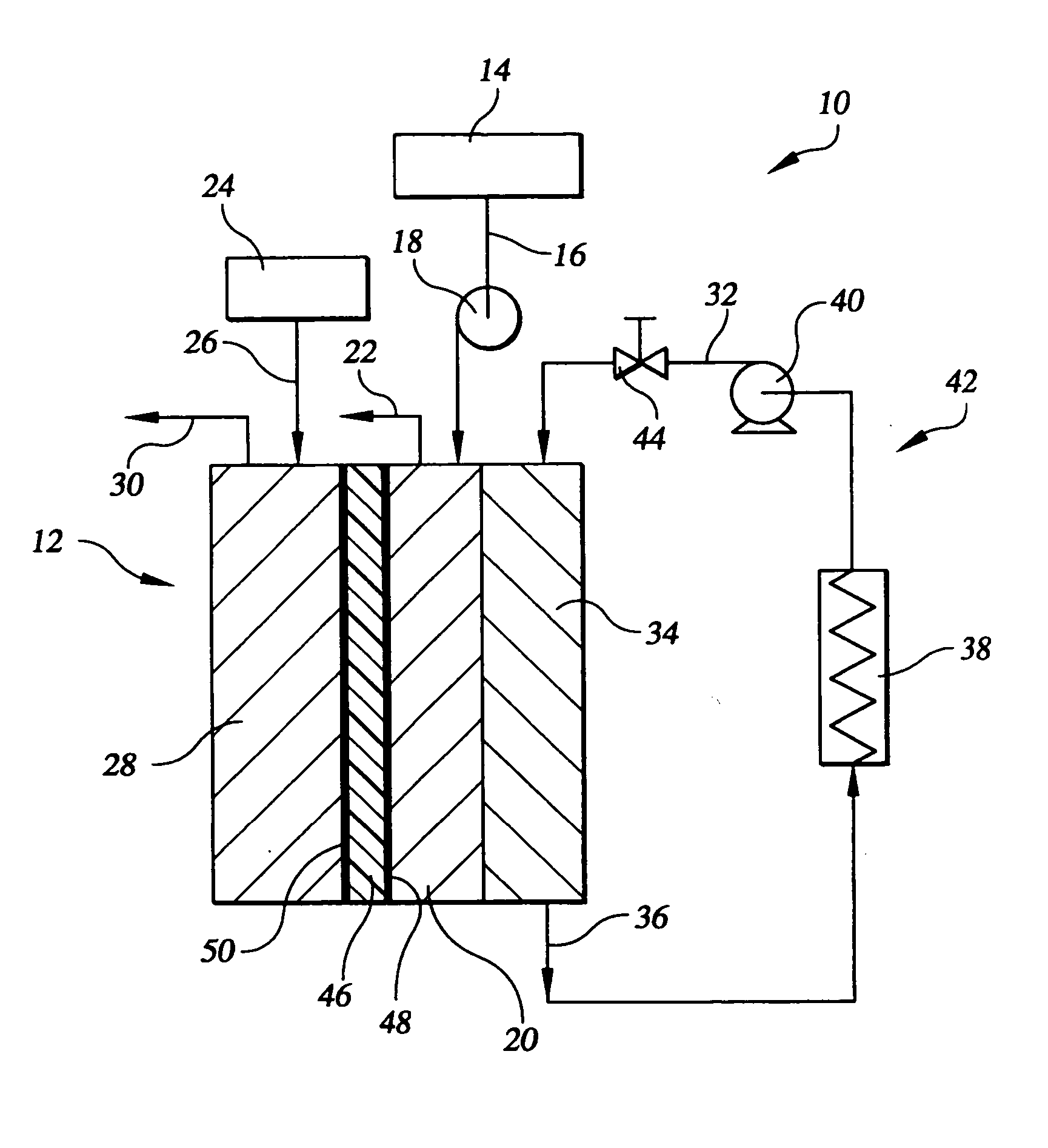
[0015] Referring to the drawings in detail, a simplified fuel cell power plant 10 is shown in FIG. 1 including at least one fuel cell 12 that is constructed in accordance with the present invention and is generally represented by the reference numeral 12. The fuel cell 12 produces electrical power from first and second reactant streams, such as oxygen containing oxidant and hydrogen containing reducing fluid reactant streams, as is known. The first reactant such as an oxidant is directed from an oxidant supply 14 through an oxidant supply line 16 that may include a blower 18 into a first reactant or cathode flow field 20 of the fuel cell 12 and out of the fuel cell 12 through an oxidant vent 22. Similarly, a second reactant such as a reducing fluid is directed from a fuel supply 24 through a fuel supply line 26 into a second reactant or anode flow field 28 of the fuel cell 12 and out of the cell through a fuel vent 30.

[0016] The power plant 10 may also direct a coolant stream such ...


PUM

PropertyMeasurementUnit
freezing temperatureaaaaaaaaaa
electrical currentaaaaaaaaaa
cross-flow lengthaaaaaaaaaa

Abstract

A fuel cell includes a membrane electrode assembly (46) having a first reactant flow field (80) secured adjacent a first or second surface (48, 50) of the assembly (46) for directing flow of a first reactant adjacent the first or second surface of the assembly (46). The first reactant flow field (80) defines a plurality of two-pass circuits (82, 84, 86, 88), and each two-pass circuit (82) is in fluid communication with both a first reactant inlet (90) for directing the first reactant into the fuel cell (12), and with a first reactant outlet (92) for directing the first reactant out of the fuel cell (12). The plurality of two-pass circuits (82) facilitate water movement (112) toward the reactant inlet (90) to aid in passive maintenance of fuel cell (12) water balance.

Description

TECHNICAL FIELD [0001] The present invention relates to fuel cells that are suited for usage in transportation vehicles, portable power plants, or as stationary power plants, and the invention especially relates to a fuel cell than enhances water balance and that minimizes any need for active circulation of water. BACKGROUND ART [0002] Fuel cells are well known and are typically arranged in a fuel cell stack in cooperation with support systems to form a fuel cell power plant. Such plants are used to produce electrical current from hydrogen containing reducing fluid fuel and oxygen containing oxidant reactant streams to power electrical apparatus such as power plants and transportation vehicles. For fuel cells of the prior art to remain in water balance, it is known that an amount of water leaving the fuel cell must not be greater than an amount of water generated by the fuel cell during operation. Additionally, water must move into, move through, and diffuse and / or evaporate out of ...

Claims


Application Information

Patent Timeline
Patent Type & Authority Applications(United States)
IPC IPC(8): H01M8/02H01M8/04H01M8/10
CPCH01M8/0258H01M8/026Y02E60/50H01M8/04291H01M8/1002H01M8/04029H01M8/0267H01M8/1007
Inventor YANG, DELIANGYI, JUNG S.
Owner AUDI AG
Why Eureka
Try Eureka