
Electrical fixture for facilitating the location of a corresponding opening in a construction panel

a technology of electrical fixtures and construction panels, which is applied in the direction of electric cable installation, cables, instruments, etc., can solve the problems of not being able to determine the exact location of the wall panel being installed in relation to the adjacent wall panel, and not being able to install a wall panel material over an electrical box

Inactive Publication Date: 2010-12-07
LAVALLE STEPHEN T
View PDF26 Cites 20 Cited by
  • Summary
  • Abstract
  • Description
  • Claims
  • Application Information

AI Technical Summary

Benefits of technology

[0014]AN OBJECT of the present invention is to provide an electrical fixture for facilitating the location of a corresponding opening in a construction panel that avoids the disadvantages of the prior art.
[0015]ANOTHER OBJECT of the present invention is to provide an electrical fixture for facilitating the location of a corresponding opening in a construction panel that is simple and inexpensive to manufacture.
[0016]STILL ANOTHER OBJECT of the present invention is to provide an electrical fixture for facilitating the location of a corresponding opening in a construction panel that is simple to use.
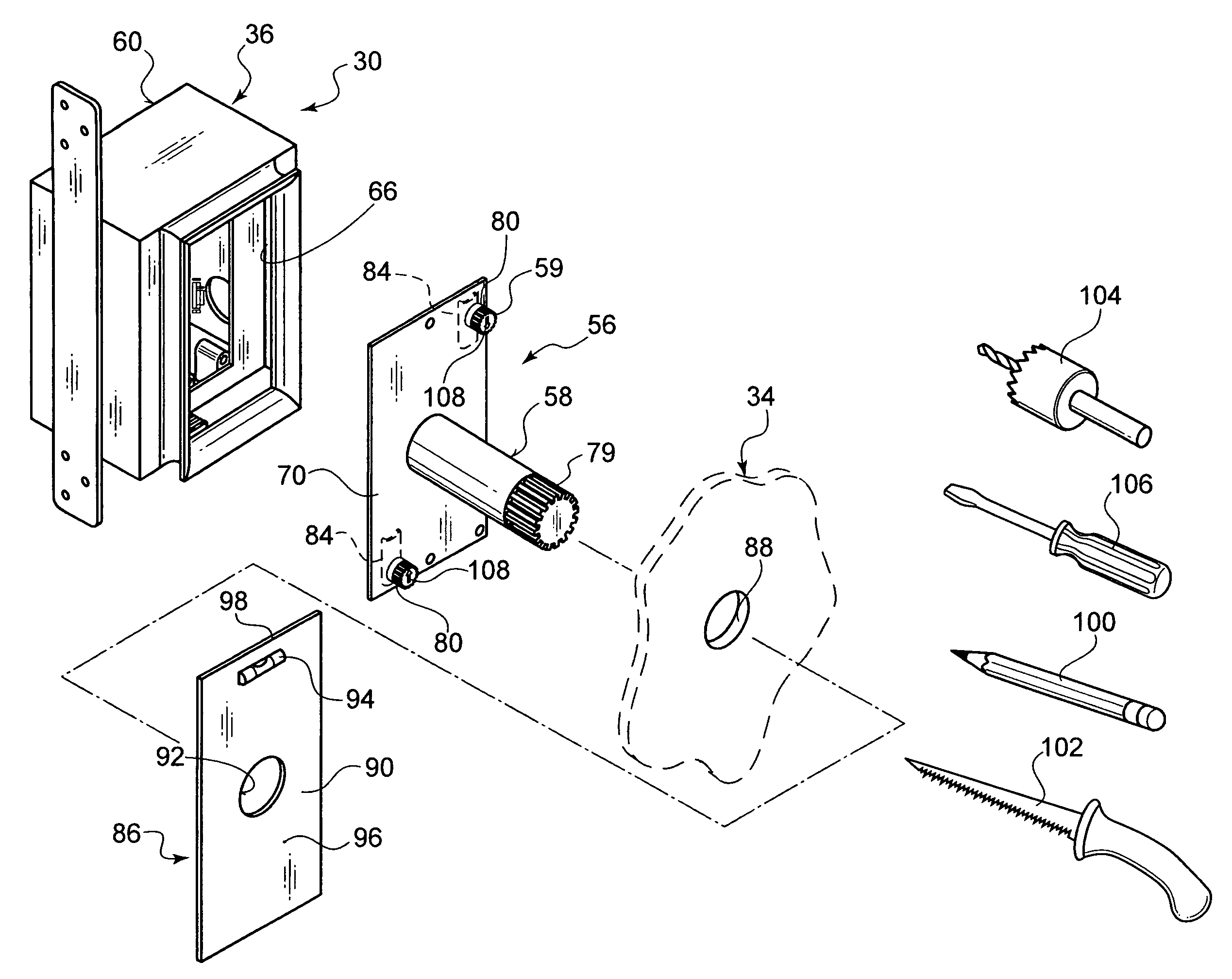
[0017]BRIEFLY STATED, STILL YET ANOTHER OBJECT of the present invention is to provide an electrical fixture for facilitating the location of a corresponding opening in a construction panel. The electrical fixture comprises a housing for mounting to a stationary building structure behind the construction panel and a collar having a back portion that will eventually fit through the corresponding opening made in the construction panel and into the housing. The back portion of the collar can be locked within the housing. A placement jig is removably secured within the housing and has a cylindrical portion extending outwardly from the housing that will extend through a small preliminary opening made in the construction panel, so that the corresponding opening can be made in the construction panel to allow the back portion of the collar to fit there through.

Problems solved by technology

Owing to this, it is not possible to install a wall panel material over an electrical box—until the final cut-out is made, lest the wall panel material protrudes its thickness beyond adjacent panels.
Unless the desired wall panel can first be placed upon the framing members and, at the same time, against the adjacent wall panels—it is impossible to determine the exact location of the wall panel being installed in relation to the adjacent wall panels.
This deficiency is universal with all prior art in that they utilize a locating post on a one piece box.

Method used


Image

  • Electrical fixture for facilitating the location of a corresponding opening in a construction panel
  • Electrical fixture for facilitating the location of a corresponding opening in a construction panel
  • Electrical fixture for facilitating the location of a corresponding opening in a construction panel

Examples


Embodiment Construction

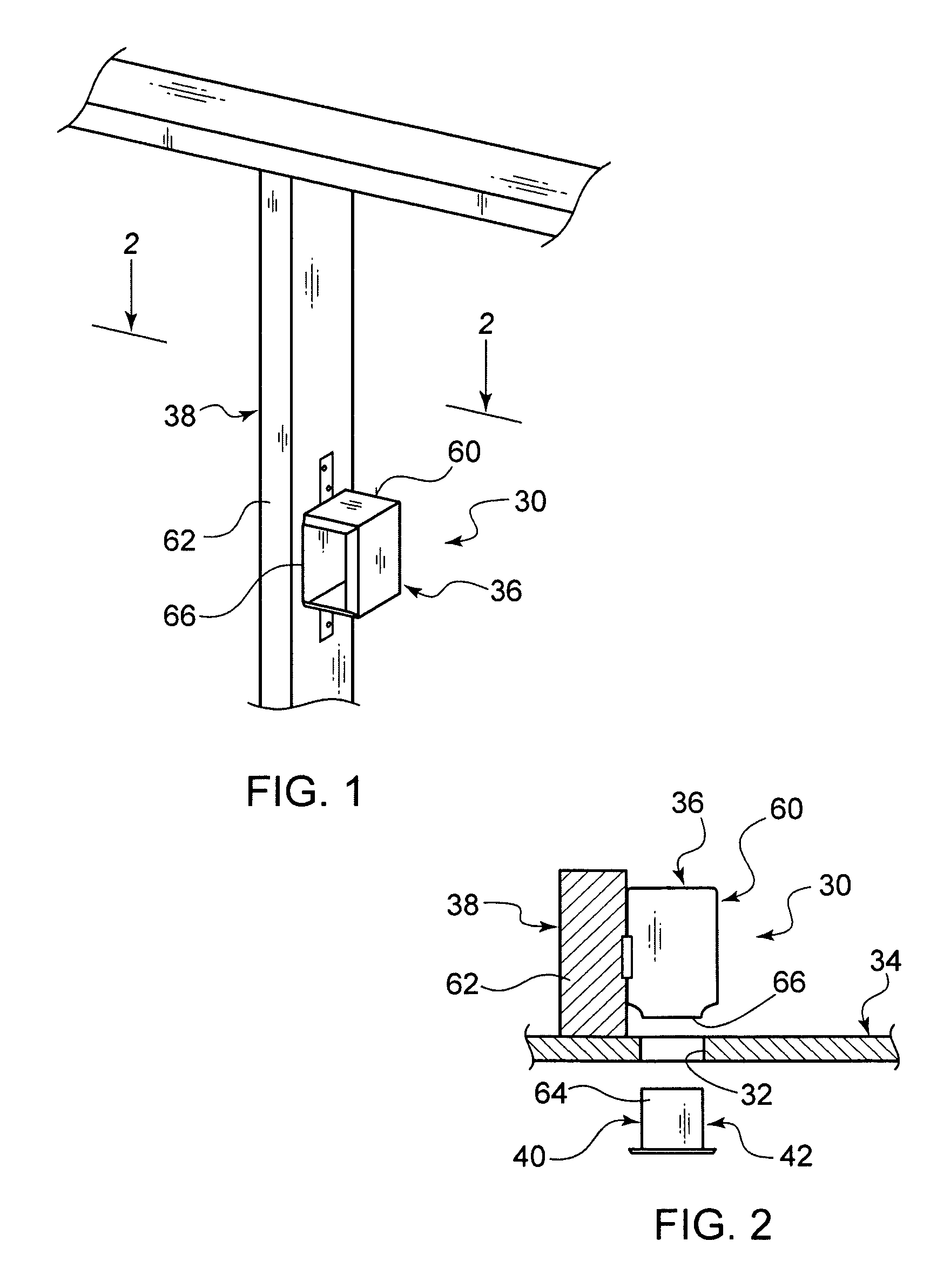
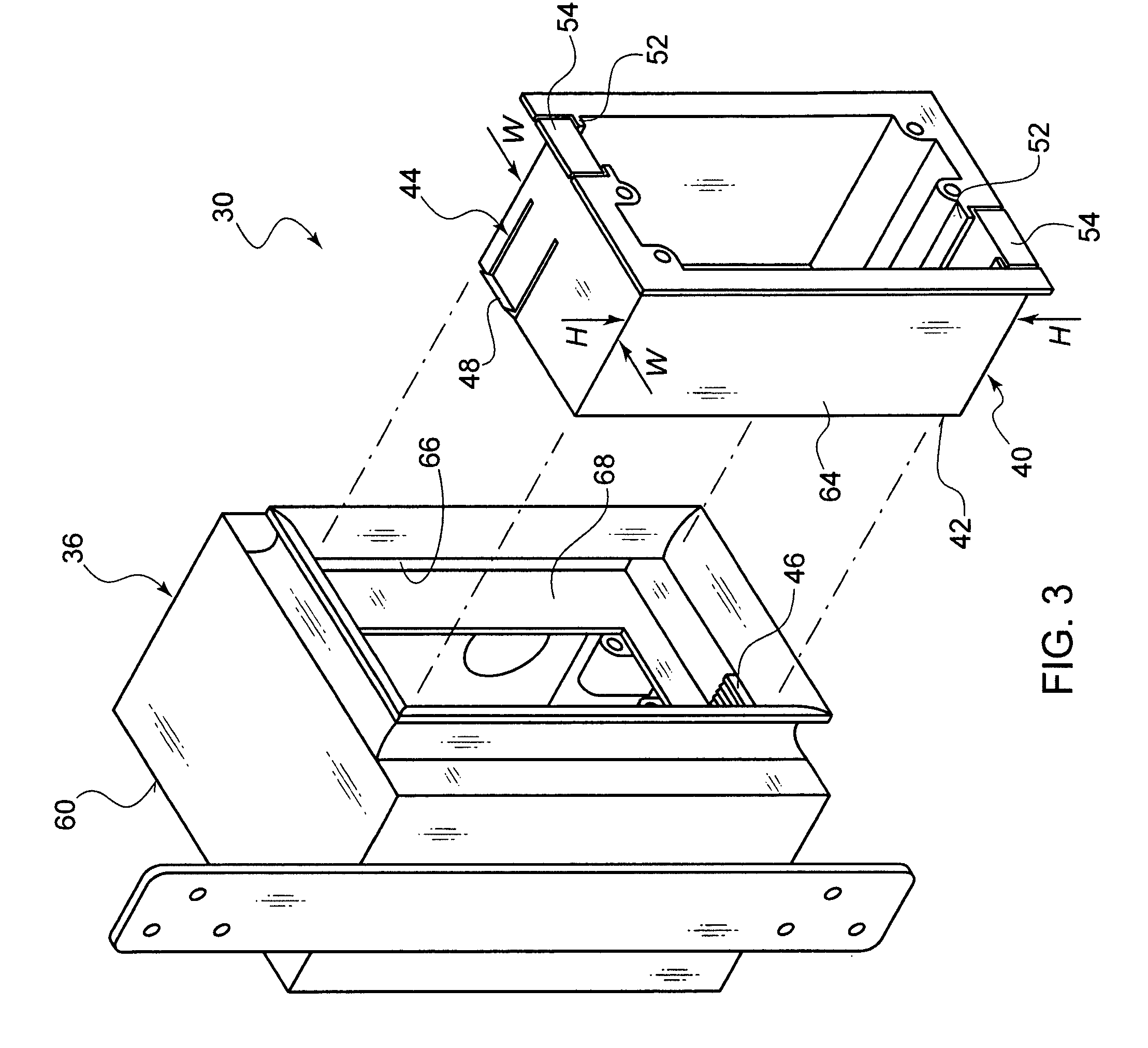
[0127]Referring now to the figures, in which like numerals indicate like parts, and particularly to FIGS. 1 through 12, which are a diagrammatic perspective view of a housing being a junction box of a first embodiment of the present invention mounted to a wall stud; a diagrammatic top cross sectional view taken in the direction of line 2-2 of FIG. 1, with a construction panel in place and a corresponding opening cut therethrough for insertion of a cooperating collar of the first embodiment; an exploded enlarged diagrammatic perspective view showing the cooperation between the housing and the collar, but with the construction panel removed therefrom; a still further enlarged diagrammatic perspective view, with parts broken away, of the housing, showing the interior structure in greater detail; a still further enlarged diagrammatic perspective view, with parts broken away, of the collar, showing the interior structure in greater detail; a diagrammatic perspective view, similar to FIG....


PUM


Abstract

An electrical fixture for facilitating the location of a corresponding opening in a construction panel. The electrical fixture comprises a housing for mounting to a stationary building structure behind the construction panel and a collar having a back portion that will eventually fit through the corresponding opening made in the construction panel and into the housing. The back portion of the collar can be locked within the housing. A placement jig is removably secured within the housing and has a cylindrical portion extending outwardly from the housing that will extend through a small preliminary opening made in the construction panel, so that the corresponding opening can be made in the construction panel to allow the back portion of the collar to fit therethrough.

Description

BACKGROUND OF THE INVENTION[0001]1. Field of the Invention[0002]The present invention relates to a locating device, and more particularly, an electrical fixture for facilitating the location of a corresponding opening in a construction panel.[0003]2. Description of the Prior Art[0004]Numerous innovations for apparatuses for locating electrical boxes access openings have been provided in the prior art that will be described. Even though these innovations may be suitable for the specific individual purposes to which they address, however, they differ from the present invention.[0005]A FIRST EXAMPLE, U.S. Pat. No. 4,059,905, Issued on Nov. 29, 1977, to Wieting teaches an apparatus that includes a locator pin assembly for mounting on the outlet box before the covering member is placed over the box. It includes one or more pins, depending on the type of outlet box, that are attached to and extend perpendicularly from opposite sides of the mounting plate. The pins are sharp on both ends a...

Claims


Application Information

Patent Timeline
IPC IPC(8): G01B1/00
CPCH02G1/00H02G3/12H02G2200/30Y10S33/10
Inventor LAVALLE, STEPHEN T.
Owner LAVALLE STEPHEN T
Learn More