Non-invasive system and method for measuring vacuum pressure in a fluid

a vacuum pressure and fluid technology, applied in the field of pressure measuring systems, can solve the problems of void, vacuum, cross contamination of fluids, etc., and achieve the effect of maximizing the scope of invention, simple construction and easy follow-up

Inactive Publication Date: 2010-12-07
TENEX HEALTH
View PDF21 Cites 28 Cited by
  • Summary
  • Abstract
  • Description
  • Claims
  • Application Information

AI Technical Summary

Benefits of technology

[0008]In order to differentiate from limitations found in the prior art and to maximize the scope of the invention presently disclosed, it is one object to provide for a system that noninvasively measures vacuum pressure in a fluid. It is considered noninvasive because this system created by the body, tubing and sensor chamber never contact external instrumentation or measuring devices. This presently disclosed system is conducive to ensuring the prevention of cross contamination of fluids from previous or subsequent use. It is another object of the present invention to avoid a system that suffers from hysteresis or volume variance. A third object of the present disclosure is to provide a system that is simply constructed and a method that is easy to follow.

Problems solved by technology

Simply measuring the vacuum in a fluid is neither new nor novel, and the methods to do so do not need to be mentioned in this application, except to say that these prior methods, when applied to a living system, have generally been invasive in nature and therefore at times were susceptible to cross contamination of the fluids in which the vacuum is being measured.
The entire process is a delicate one, as the pressure in the eye must be constantly measured and maintained to prevent a number of problems.
For example, during the removal operation, any blockage in the hollow needle, possibly created during the passage of one cataract fragmentation, may cause a void, or vacuum, to build in said needle.
Failure to adequately measure and control the fluid pressure during this process may result in the sudden ejection of the blockage followed by a rapid influx of fluid from the eye into the void.
If this fluid is not replaced with sufficient speed, it could lead to the subsequent collapse of the eye chamber.
Again, however, if the fluid pressure is not adequately measured and controlled, the ramifications could be extremely problematic.
In this situation, the vacuum pressure would be negative, so when the blockage is removed there may be a subsequent flooding of the eye chamber leading to an inflation of the eye.
Furthermore, as discussed above, the use of a standard pressure measuring system to monitor these pressures is not an adequate solution to the problem, as cross contamination of fluids will then become an issue.
However, all of these solutions have been shown to suffer from deficiencies when utilized in this application.
The two aforementioned systems, though operable, suffer from increased levels of hysteresis (path dependence) and volume variance.
However, this third system can suffer from being overly robust in construction.

Method used


Image

  • Non-invasive system and method for measuring vacuum pressure in a fluid
  • Non-invasive system and method for measuring vacuum pressure in a fluid
  • Non-invasive system and method for measuring vacuum pressure in a fluid

Examples


Embodiment Construction

[0022]In the following description of the various embodiments, reference is made to the accompanying drawings, which form a part hereof, and in which is shown by way of illustration, various embodiments in which the invention may be practiced. It is to be understood that other embodiments may still be utilized and structural and functional modifications may be made without departing from the scope and spirit of the present invention.

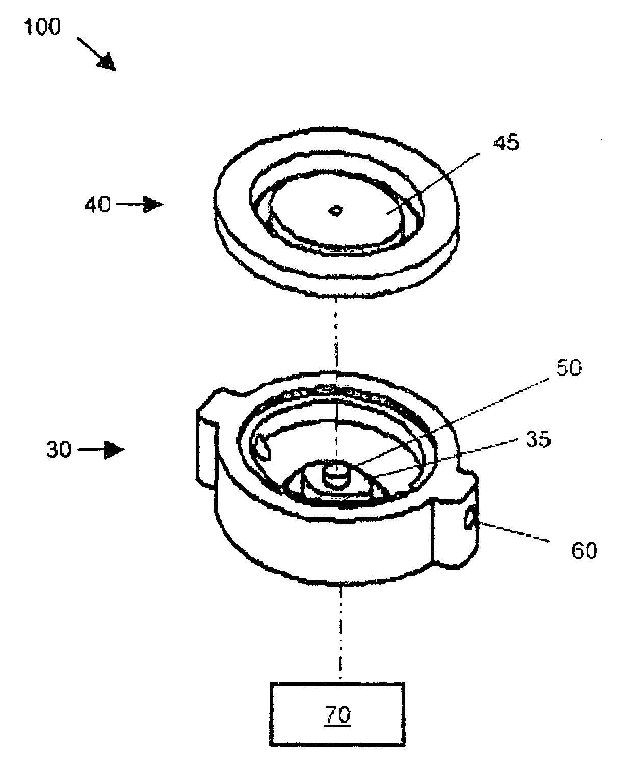
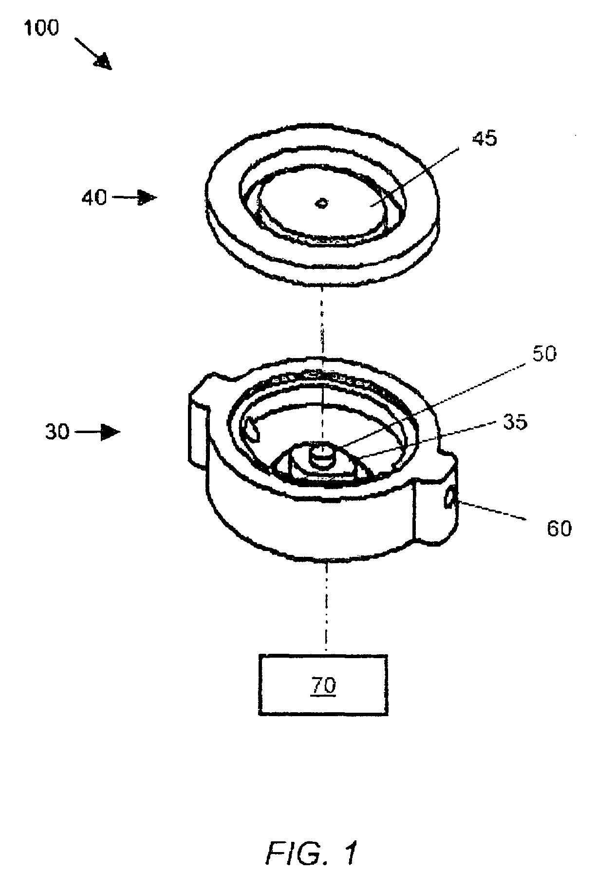
[0023]Referring to FIG. 1, an exploded view of a pressure sensor of the preferred embodiment of a system for noninvasively measuring the vacuum pressure in a fluid is shown. Pressure sensor chamber 100 is shown comprised of lower piece 30 and upper piece 40. Lower piece 30 comprises small diaphragm 35 while upper piece 40 comprises large diaphragm 45, whereby small diaphragm 35 and large diaphragm 45 are interconnected by diaphragm bridge 50. In the preferred embodiment, the entire pressure sensor is less than one inch in diameter and may be ovular or ci...


PUM

PropertyMeasurementUnit
thicknessaaaaaaaaaa
vacuum pressureaaaaaaaaaa

Abstract

A noninvasive system and method for measuring vacuum pressure in a fluid in accordance with the present invention generally includes a chamber with two interconnected diaphragms having different surface areas and a force transducer that makes contact with the smaller area diaphragm. When a pressure level less than atmospheric occurs inside the chamber, the smaller area diaphragm presses with a force on the force sensor. As the pressure level in the chamber decreases, the force on the sensor increases. The present system is intended for, but not limited to, use in a Phacoemulsification machine, where it will serve to measure the vacuum in a fluid without contaminating the fluid with previous uses of the system or with any components of the system which are unable to undergo a sterilization process.

Description

CROSS REFERENCE TO RELATED APPLICATIONS[0001]This application claims the benefit of 35 U.S.C. §119 and the filing date of provisional application 61 / 002,038, filed Nov. 6, 2007.FIELD OF INVENTION[0002]The present invention relates to the field of pressure measuring systems. More specifically, the invention relates to systems that non-invasively measure the degree of vacuum in a fluid.BACKGROUND OF THE INVENTION[0003]In essence, a vacuum is a volume of space that is void of any matter such that the gaseous pressure of this volume of space is less than standard atmospheric pressure. Simply measuring the vacuum in a fluid is neither new nor novel, and the methods to do so do not need to be mentioned in this application, except to say that these prior methods, when applied to a living system, have generally been invasive in nature and therefore at times were susceptible to cross contamination of the fluids in which the vacuum is being measured. Thus, there exists a need in the art, espe...

Claims


Application Information

Patent Timeline
Patent Type & Authority Patents(United States)
IPC IPC(8): G01L13/02
CPCA61F9/00745A61B2019/464A61B2090/064
Inventor SANDU, COSTINPARHAM, TATE
Owner TENEX HEALTH
Why Eureka
Try Eureka