Apparatus for cooling and scrubbing a flow of syngas and method of assembling

a technology of radiant syngas and apparatus, which is applied in the direction of lighting and heating apparatus, combustible gas production, and combustible gas purification/modification, etc., can solve the problem of reducing the on-stream time of the plant, the temperature at the exit of the radiant syngas cooler is still too high to allow the syngas to be handled in conventional steel piping and equipment, and the solids entrapped are still sticky

Active Publication Date: 2010-12-07
AIR PROD & CHEM INC
View PDF25 Cites 13 Cited by
  • Summary
  • Abstract
  • Description
  • Claims
  • Application Information

AI Technical Summary

Problems solved by technology

Second, in commercial practice, the convective syngas cooler has been found to be prone to plugging, which significantly reduces plant on-stream time.
But, removal of the convective syngas cooler presents two problems.
First, the approximately 950-1350° F. temperature at the exit of the radiant syngas cooler is still too high to allow the syngas to be handled in conventional steel piping and equipment.
Second, at that temperature, some of the entrained solids are still sticky, and they can plug the piping connecting the radiant syngas cooler to the syngas scrubber.

Method used


Image

  • Apparatus for cooling and scrubbing a flow of syngas and method of assembling
  • Apparatus for cooling and scrubbing a flow of syngas and method of assembling
  • Apparatus for cooling and scrubbing a flow of syngas and method of assembling

Examples


Embodiment Construction

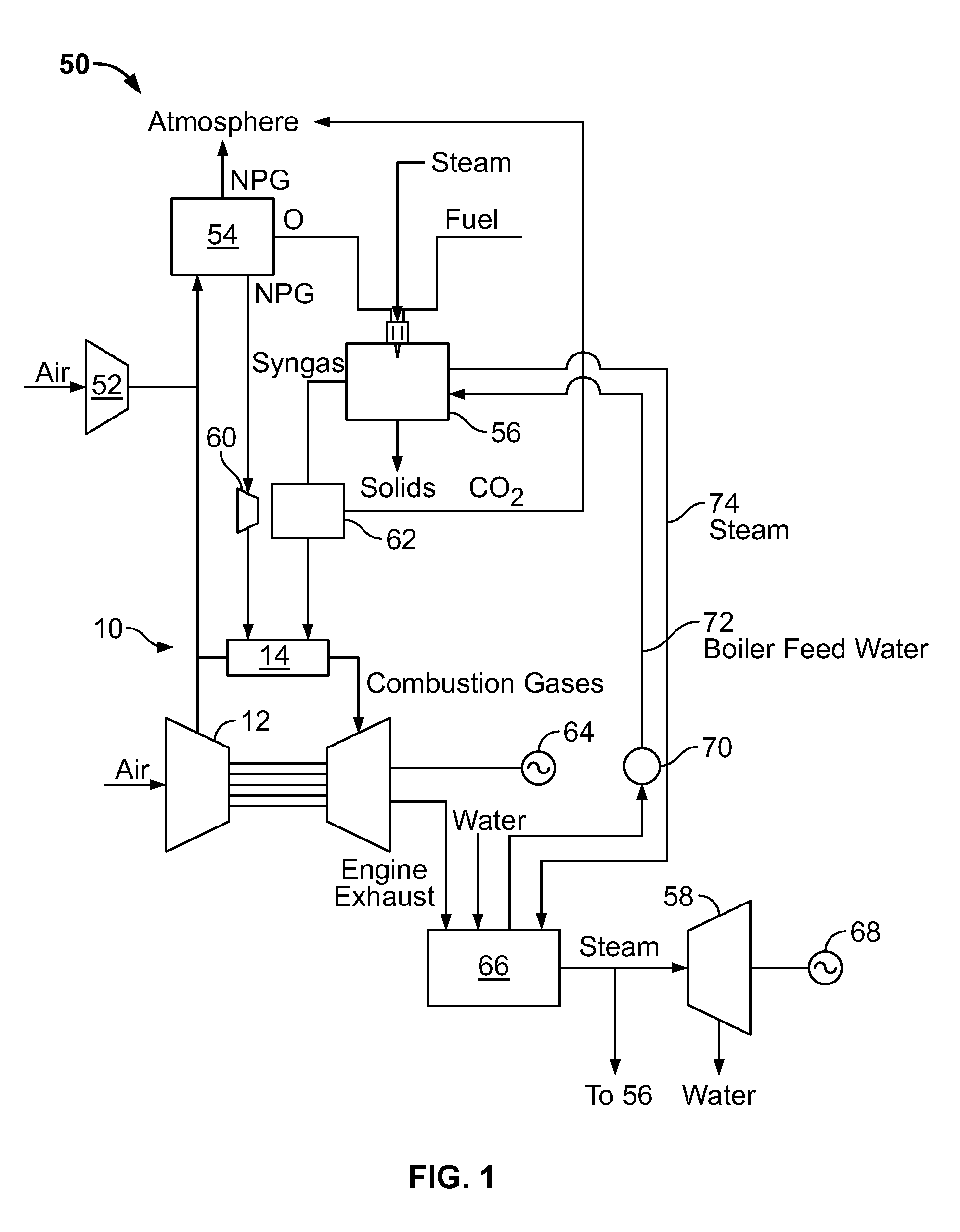
[0020]FIG. 1 is a schematic diagram of an exemplary known integrated gasification combined cycle power system 50, such as those used in a power plant. System 50 generally includes a main air compressor 52, an air separation unit 54 coupled in flow communication to compressor 52, a gasifier 56 coupled in flow communication to air separation unit 54, a gas turbine engine 10 coupled in flow communication to gasifier 56, and a steam turbine 58.

[0021]In operation, compressor 52 compresses ambient air that is channeled to air separation unit 54. In some embodiments, in addition to compressor 52 or alternatively, compressed air from gas turbine engine compressor 12 is supplied to air separation unit 54. Air separation unit 54 uses the compressed air to generate oxygen for use by gasifier 56. More specifically, air separation unit 54 separates the compressed air into separate gas flows of oxygen (O2) and a gas by-product, sometimes referred to as “process gas.” The process gas generated by ...


PUM

PropertyMeasurementUnit
temperaturesaaaaaaaaaa

Abstract

A method of assembling a spray quench apparatus is provided. The method includes coupling a first end of an exit tube to a quench chamber such that the exit tube end is in flow communication with the quench chamber, coupling at least one spray nozzle to an opposite second end of the exit tube such that water emitted from the spray nozzle fills the exit tube and forms a film of water across an inner surface of the exit tube, coupling a water source to the quench chamber for providing a substantially continuous water film along an inner surface of the quench chamber, and coupling at least one discharge apparatus to the quench chamber for providing water spray into the quench chamber, wherein the water of the water film and water sprays drains into a water sump.

Description

BACKGROUND OF THE INVENTION[0001]The present invention relates generally to gasification power systems, such as those used in a power plant, and more specifically, to gasifiers used in integrated gasification combined cycle (IGCC) power systems.[0002]At least some known combined cycle power systems include a gasification system that is integrated with at least one power-producing turbine system. For example, known gasifiers convert a mixture of fuel, air or oxygen, steam, and / or limestone into an output of partially combusted gas, sometimes referred to as “syngas”. The hot syngas is cooled and cleaned to remove contaminants and then supplied to the combustor of a gas turbine engine, which powers a generator that supplies electrical power to a power grid. Exhaust from at least some known gas turbine engines is supplied to a heat recovery steam generator that heats boiler feed water and generates steam for driving a steam turbine. Power generated by the steam turbine also drives an el...

Claims


Application Information

Patent Timeline
Patent Type & Authority Patents(United States)
IPC IPC(8): C01B3/24C10J3/76
CPCC10J3/52C10J3/78C10J3/84C10J3/845C10K1/101C10K1/005Y10T29/49826C10J2300/165C10J2300/1675Y02E20/16Y02E20/18
Inventor LEININGER, THOMAS FREDERICKJIMENEZ-HUYKE, ALLYSON JOYCORRY, JUDETH BRANNONLOPEZ, FULTON JOSEAVAGLIANO, AARON JOHNSTEVENSON, JOHN SAUNDERSCHEN, LIEN-YAN
Owner AIR PROD & CHEM INC
Why Eureka
Try Eureka