
Heater and memory cell, memory device and recording head including the heater

Inactive Publication Date: 2010-12-07
GLOBALFOUNDRIES INC
View PDF6 Cites 4 Cited by
  • Summary
  • Abstract
  • Description
  • Claims
  • Application Information

AI Technical Summary

Benefits of technology

The present invention provides a heater with a controllable hot spot location based on the polarity of current (e.g., electrical current) in the heater. This is achieved by using a heating element with a different material from the leads of the heater, which allows for better control over the hot spot location. The heater can be used in memory cells, memory devices, and recording heads for information storage devices. The technical effect is improved precision and control over the hot spot location in the heater.

Problems solved by technology

One of the key challenges in the use of nanoheaters and / or nanoscale thermal transducers for local heat delivery is the control of the location and the spatial extent of the resulting hot spot.

Method used


Image

  • Heater and memory cell, memory device and recording head including the heater
  • Heater and memory cell, memory device and recording head including the heater
  • Heater and memory cell, memory device and recording head including the heater

Examples


Embodiment Construction

[0028]Referring now to the drawings, FIGS. 1-10B illustrate the exemplary aspects of the present invention.

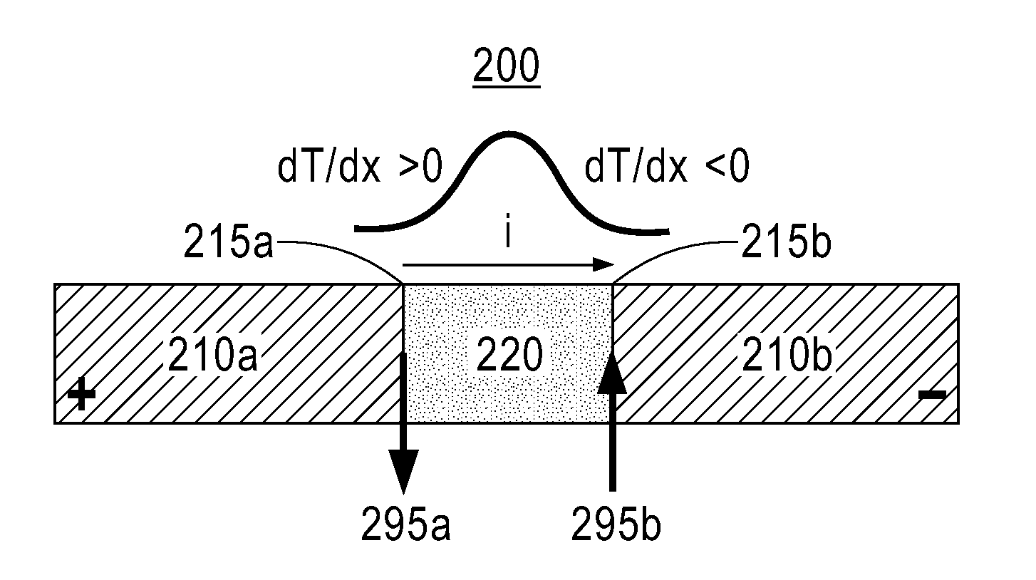
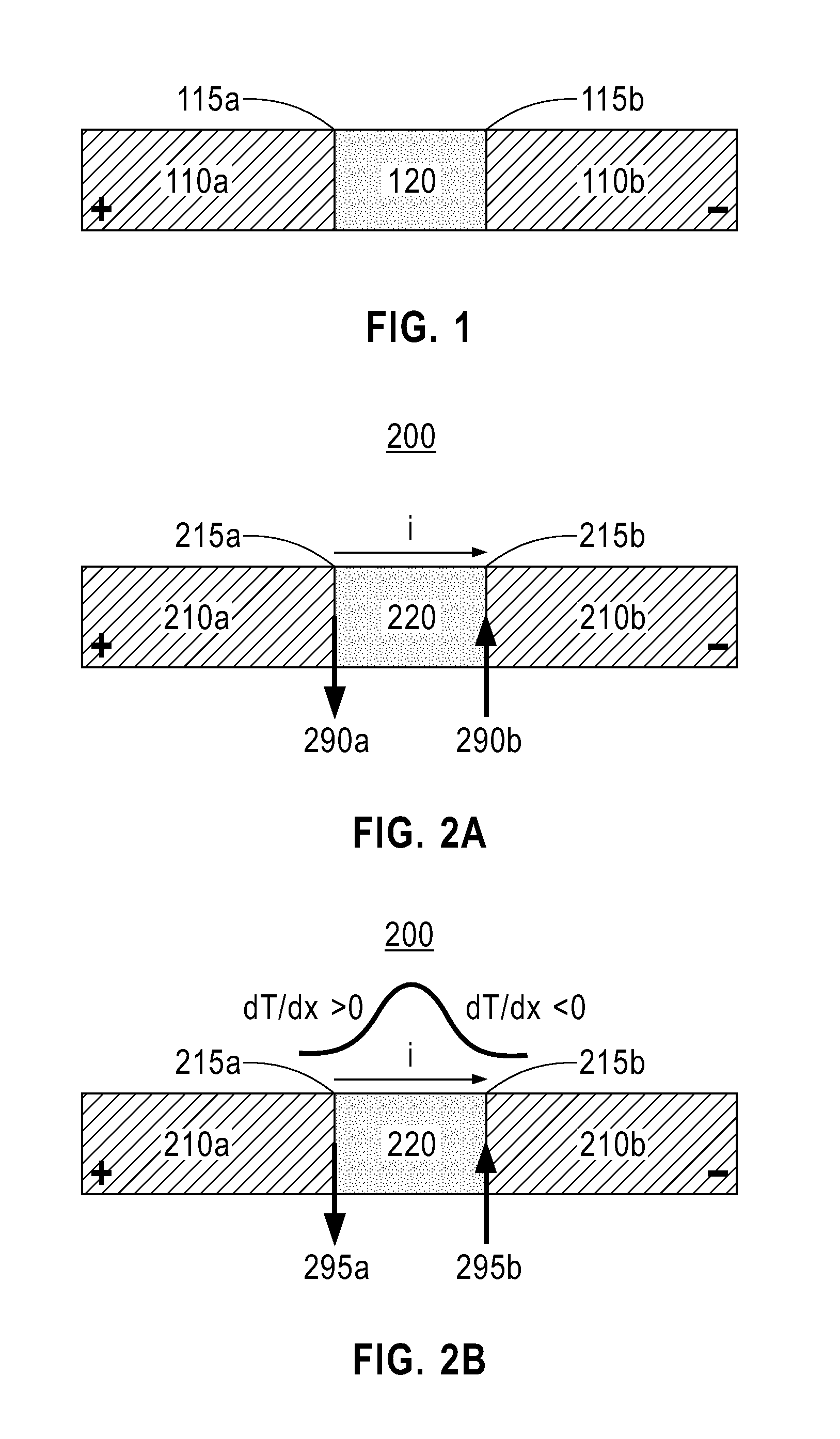
[0029]FIG. 1 illustrates a heater 100, which could be used in a memory cell or information storage device (e.g., harddisk drive, CD-Rom drive, DVD drive etc.) in accordance with the exemplary aspects of the present invention. The heater 100 includes at least two leads 110a and 110b (e.g., a pair of leads), and a heating element 120 which is formed adjacent to the leads (e.g., between the at least two leads). Further, an interface 115a may exist between the heating element 120 and the lead 110a, and another interface 115b may exist between the heating element 120 and the lead 110b.

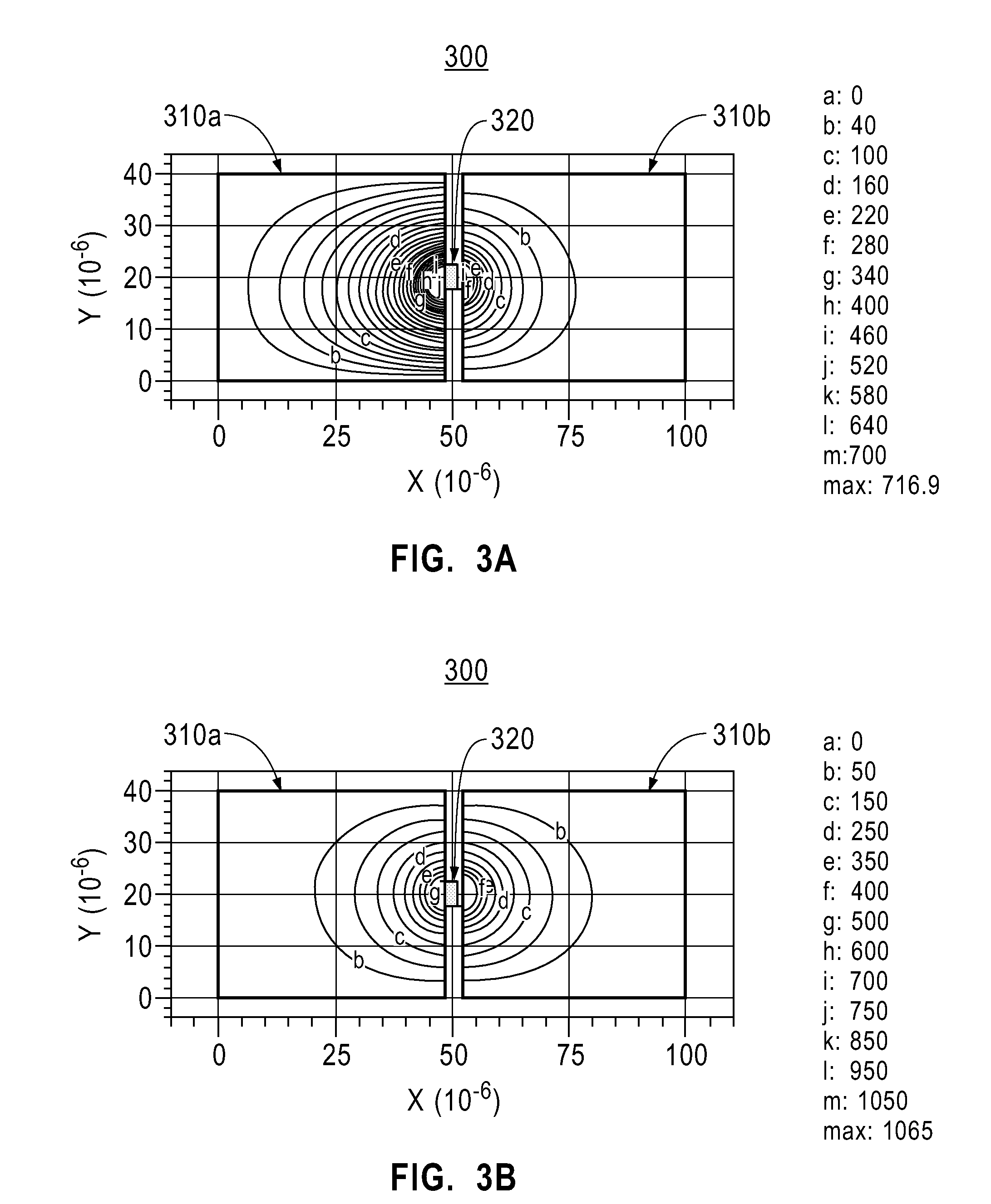
[0030]Importantly, a material of the heating element 120 may be different from a material of the leads 110a, 110b such that a location of a hot spot in the heater 100 is controllable based on a polarity of current in the heater 100 (e.g., electrical current applied to leads 110a, 110b).

[0031]For examp...


PUM

PropertyMeasurementUnit
thicknessaaaaaaaaaa
widthaaaaaaaaaa
widthaaaaaaaaaa

Abstract

A heater includes at least two leads, and a heating element which is formed between the at least two leads, a material of the heating element being different from a material of the at least two leads such that a location of a hot spot in the heater is controllable based on a polarity of current in the heater.

Description

BACKGROUND OF THE INVENTION[0001]1. Field of the Invention[0002]The present invention relates to a heater, and more particularly, to a heater in which a material of the heating element is different from a material of the leads such that a location of a hot spot in the heater is controllable based on a polarity of current in the heater.[0003]2. Description of the Related Art[0004]The importance of nanoheaters and / or nanoscale thermal transducers for local heat delivery has been realized for magnetic thermal recording, ferroelectric thermal recording, phase-change recording and reading, and thermal memory (e.g., see U.S. Pat. Nos. 6,532,125, 6,233,206, 6,597,639 and 6,433,310, and U.S. Patent Publication No. US20040188668A1, all of which are commonly assigned to the present assignee and are incorporated by reference herein).[0005]The importance of nanoheaters and / or nanoscale thermal transducers for local heat delivery has also been realized for thermo-mechanical storage applications ...

Claims


Application Information

Patent Timeline
Patent Type & Authority Patents(United States)
IPC IPC(8): H05B3/10G11C11/00
CPCB82Y10/00H01L45/1286G11B7/00454H01L45/1206G11B7/00557H01L45/144H01L45/122H01L45/06G11B7/22G11C13/0004H05B2214/04Y10T29/49083H10N70/253H10N70/821H10N70/231H10N70/8613H10N70/8828
Inventor GUHA, SUPRATIKHAMANN, HENDRIK F.
Owner GLOBALFOUNDRIES INC
Learn More