
Magnetic disk apparatus

a magnetic disk and apparatus technology, applied in the direction of maintaining head carrier alignment, recording signal processing, instruments, etc., can solve the problems of thermal fluctuation resistance, high aspect ratio forming magnetic dots, and inability to deal disadvantageously with skew angle,

Inactive Publication Date: 2010-12-07
KK TOSHIBA
View PDF17 Cites 4 Cited by
  • Summary
  • Abstract
  • Description
  • Claims
  • Application Information

AI Technical Summary

Benefits of technology

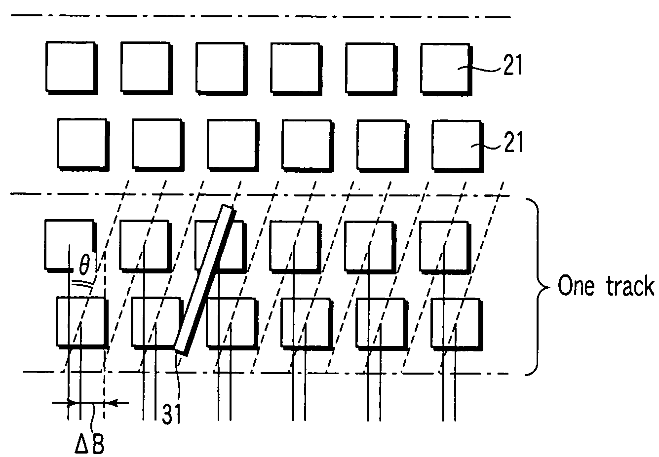
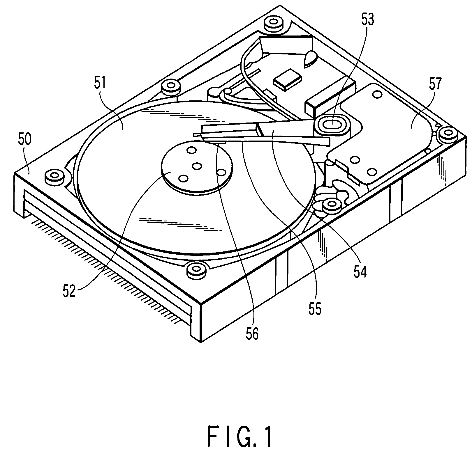
The present invention relates to a magnetic disk apparatus that uses a bit patterned medium to solve problems such as interference between adjacent tracks and thermal fluctuation resistance. The invention proposes a magnetic disk with magnetic dot lines that include magnetic dots arrayed at equal intervals in a down track direction. The invention also proposes a read / write head that sequentially performs read and write on the magnetic dots in each magnetic dot line as one track, where the magnetic dots in each line are displaced from those in adjacent lines by a half pitch. The invention solves the problem of a skew angle that may occur when accessing the inner or outer peripheral side of the magnetic disk. The bit patterned medium provides a sufficient interval between magnetic dots to deal with the skew angle. The invention is useful for manufacturing bit patterned media with a high aspect ratio of magnetic dots.

Problems solved by technology

For magnetic disks in these magnetic disk apparatuses, problems such as the interference between adjacent tracks and thermal fluctuation resistance have become serious.
However, when an attempt is made to manufacture bit patterned media having a bit pattern equivalent to that of the current magnetic disks, forming magnetic dots of a high aspect ratio is very difficult and is impractical.
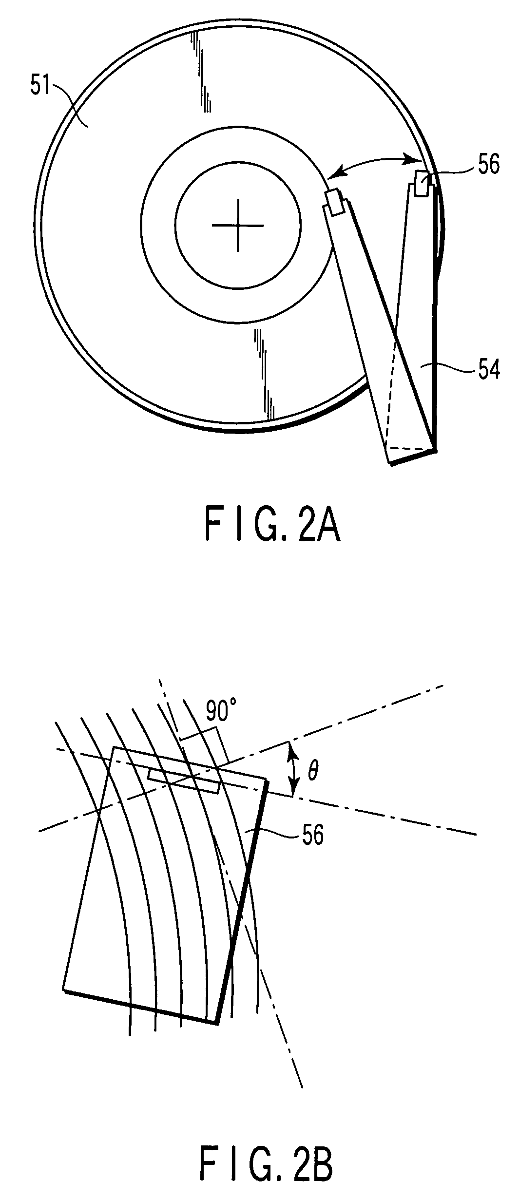
Thus, the bit patterned medium disadvantageously cannot deal with a skew angle that may occur when the head accesses the inner or outer peripheral side of the magnetic disk.

Method used


Image

  • Magnetic disk apparatus
  • Magnetic disk apparatus
  • Magnetic disk apparatus

Examples


Embodiment Construction

[0018]Various embodiments according to the invention will be described hereinafter with reference to the accompanying drawings. In general, according to one embodiment of the present invention, there is provided a magnetic disk apparatus comprising: a magnetic disk comprising magnetic dot lines each including magnetic dots arrayed at equal intervals in a down track direction; and a read / write head which uses a plurality of adjacent magnetic dot lines as one track and sequentially performs read and write on the magnetic dots included in the magnetic dot lines constituting the track, wherein the magnetic dots included in each of the magnetic dot lines in each track of the magnetic disk are displaced in the down track direction from the magnetic dots included in the adjacent dot line in the track depending on a possible skew angle between the read / write head and the track so that the magnetic dots are sequentially accessed by the read / write head.

[0019]FIG. 1 is a perspective view of a ...


PUM

PropertyMeasurementUnit
aspect ratioaaaaaaaaaa
lengthaaaaaaaaaa
lengthaaaaaaaaaa

Abstract

According to one embodiment, there is provided a magnetic disk apparatus having a magnetic disk having magnetic dot lines each including magnetic dots arrayed at equal intervals in a down track direction, and a read / write head which uses a plurality of adjacent magnetic dot lines as one track and sequentially performs read and write on the magnetic dots included in the magnetic dot lines constituting the track, in which the magnetic dots included in each of the magnetic dot lines in each track of the magnetic disk are displaced in the down track direction from the magnetic dots included in the adjacent dot line in the track depending on a possible skew angle between the read / write head and the track so that the magnetic dots are sequentially accessed by the read / write head.

Description

CROSS-REFERENCE TO RELATED APPLICATIONS[0001]This application is based upon and claims the benefit of priority from Japanese Patent Application No. 2006-182737, filed Jun. 30, 2006, the entire contents of which are incorporated herein by reference.BACKGROUND[0002]1. Field[0003]One embodiment of the present invention relates to a magnetic disk apparatus, and in particular, to a magnetic disk apparatus using a bit patterned medium.[0004]2. Description of the Related Art[0005]In current magnetic disk apparatuses (hard disk drives), bits are written to a recording layer with a magnetic head. For magnetic disks in these magnetic disk apparatuses, problems such as the interference between adjacent tracks and thermal fluctuation resistance have become serious.[0006]Proposals have been made of bit patterned media in which a magnetic material is processed into arrayed magnetic dots separated from one another each of which is used as one bit. Such bit patterned media are expected to solve the...

Claims


Application Information

Patent Timeline
Patent Type & Authority Patents(United States)
IPC IPC(8): G11B21/02
CPCB82Y10/00G11B5/59627G11B5/74G11B5/743G11B5/746G11B5/82
Inventor SAKURAI, MASATOSHIKIKITSU, AKIRAKASHIWAGI, KAZUTO
Owner KK TOSHIBA
Learn More