
Method for enabling the operation of automation components of a technical system via a mobile control and monitoring device

a technology of which is applied in the direction of program control, electric controller, instruments, etc., can solve the problems of disabled operation of the automation components via the mobile control and monitoring module, and achieve the effects of enhanced hmi system, enhanced mobile control and monitoring device, and enhanced automation components

Active Publication Date: 2010-12-07
SIEMENS AG
View PDF13 Cites 6 Cited by
  • Summary
  • Abstract
  • Description
  • Claims
  • Application Information

AI Technical Summary

Benefits of technology

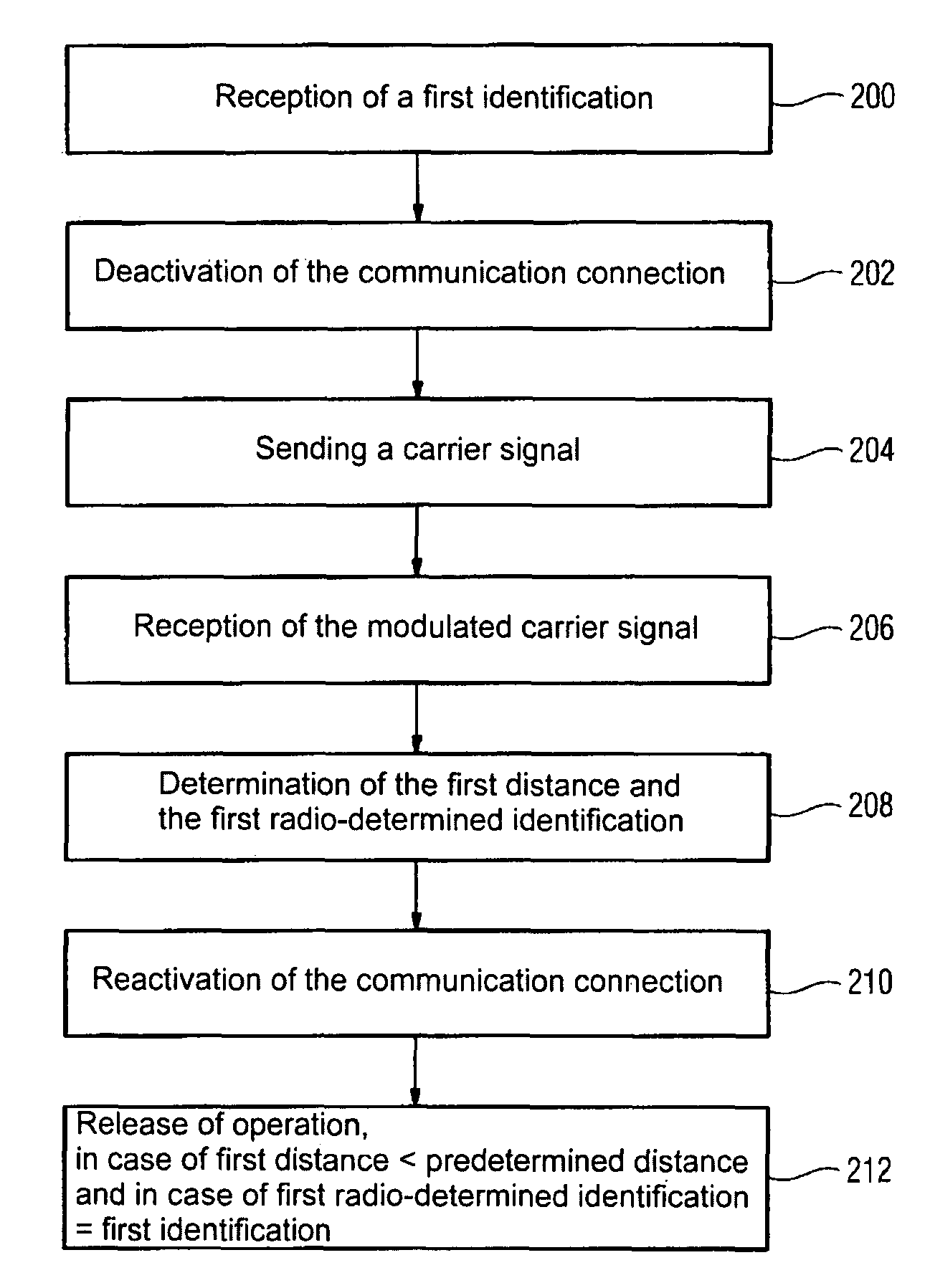
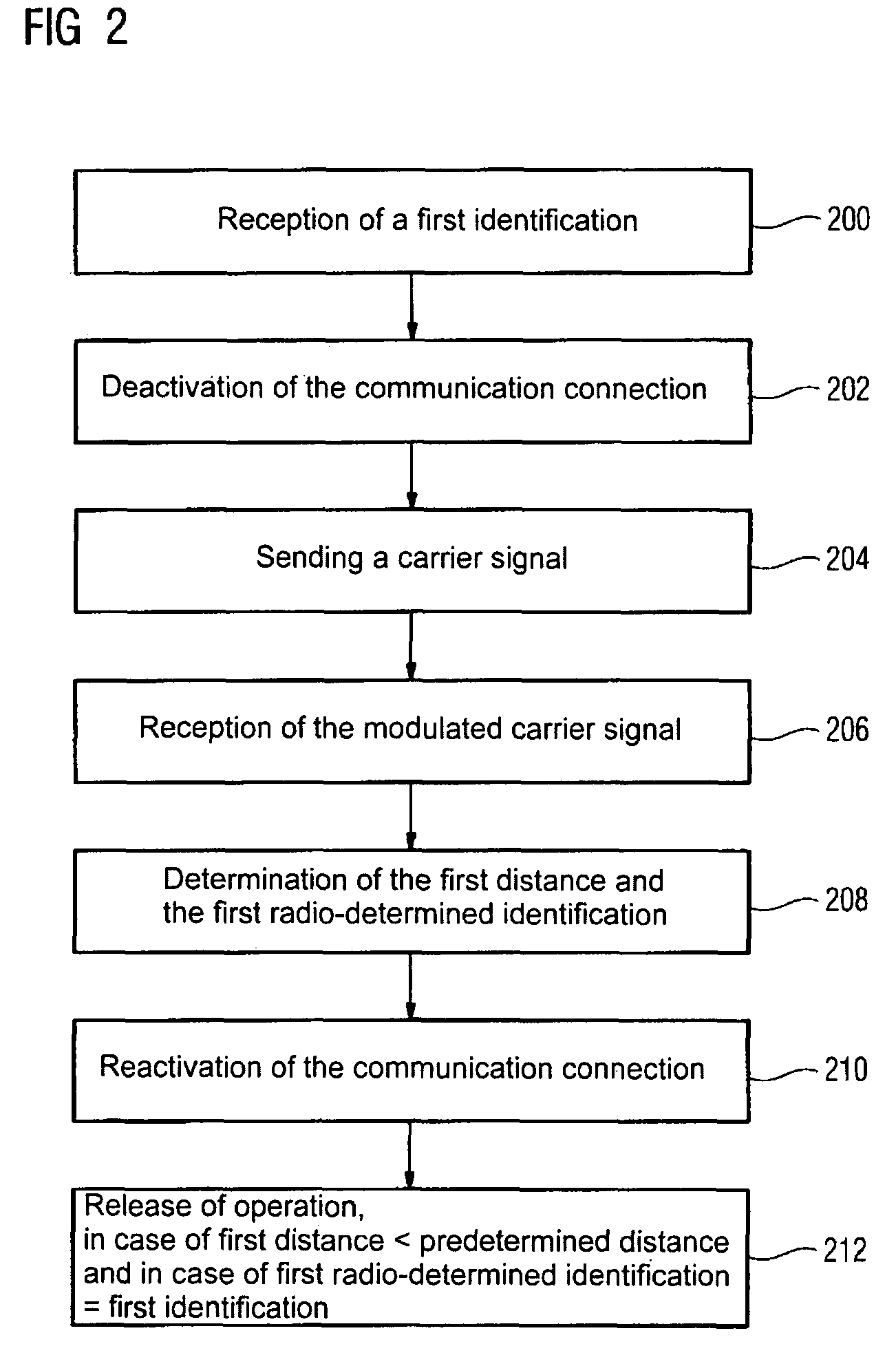
"The invention provides an improved method for controlling and monitoring automation components of a technical system using a mobile control and monitoring device. The method involves receiving a first identification from a first transponder device, which has been activated by the automation components and deactivating the communication connection between the control and monitoring device and the automation components. The mobile control and monitoring device then sends a carrier signal, which is modulated by the first transponder device. The first distance between the control and monitoring device and the first transponder device is determined, and the first radio-determined identification of the first transponder device is determined. The operation of the automation components is enabled if the first distance is shorter than a predetermined distance and the first radio-determined identification matches the first identification. The invention also provides a mobile control and monitoring device and an enhanced HMI system for the technical system."

Problems solved by technology

Otherwise the operation of the automation components via the mobile control and monitoring module is disabled.

Method used


Image

  • Method for enabling the operation of automation components of a technical system via a mobile control and monitoring device
  • Method for enabling the operation of automation components of a technical system via a mobile control and monitoring device
  • Method for enabling the operation of automation components of a technical system via a mobile control and monitoring device

Examples


Embodiment Construction

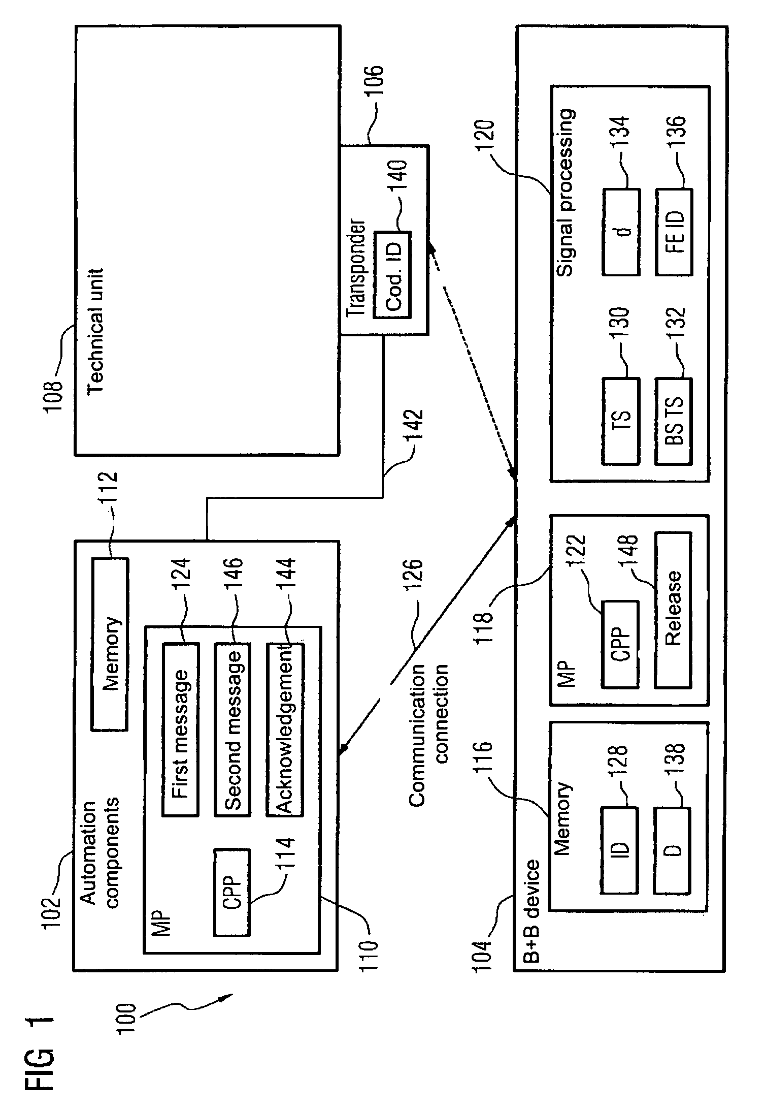
[0038]FIG. 1 shows a block diagram of an HMI system 100. In this diagram, the HMI system 100 comprises the automation components 102, a control and monitoring device 104 and a transponder device 106. The automation components 102 are provided for the control of a technical system 108. The transponder device 106 is attached to the technical system and can be activated or deactivated via the automation components 102. To this end, the transponder device 106 is connected to the automation components 102 via the connection 142. Connection 142 is for example a twisted pair cable for industrial use through which a supply voltage can be applied to the transponder device 106. The transponder device 106 operates autonomously when the supply voltage is applied.

[0039]The mobile control and monitoring device 104 is also provided for the operation and monitoring of the automation components 102 or the control, diagnostic, alarm processing and long-term processes running thereupon.

[0040]The autom...


PUM


Abstract

There is described a method for enabling the operation of automation components of a technical system via a mobile control and monitoring device. In a first step, the control and monitoring device receives a first identification from a first transponder device, with the first transponder device being attached to the technical system, with the first transponder device having been activated by the automation components and with the first identification having been transmitted via a wireless communication connection from the automation components to the mobile control and monitoring device. In a further step the communication connection between the control and monitoring device and the automation components is deactivated. The mobile control and monitoring device sends a carrier signal and following that receives the carrier signal modulated by the first transponder device. A first distance between the control and monitoring device and the first transponder device is then determined from the modulated carrier signal. In addition, a first radio-determined identification from the first transponder device is determined from the modulated carrier signal. Following the reception of the modulated carrier signal, the communication connection is reactivated. If the first distance is shorter than a predetermined first distance and if the radio-determined first identification corresponds to the first identification, the operation of the automation components is enabled.

Description

CROSS REFERENCE TO RELATED APPLICATIONS[0001]This application claims priority of European application No. 06019937.9 EP filed Sep. 22, 2006, which is incorporated by reference herein in its entirety.FIELD OF INVENTION[0002]The invention relates to a method for enabling the operation of automation components of a technical system by means of a mobile control and monitoring device, a control and monitoring device, automation components and a computer program product for carrying out the method in accordance with the invention.BACKGROUND OF INVENTION[0003]Technical systems are all types of technical devices and systems both arranged individually and within a data processing network, for example, via a field bus. In the case of industrial applications these include individual operating resources, for example, drives and processing machines. However, a technical system can also be a production unit in which an overall technical process is operated using locally distributed operating mean...

Claims


Application Information

Patent Timeline
Patent Type & Authority Patents(United States)
IPC IPC(8): G05B11/01G08B3/00G05B19/18G05B15/00G05B23/02
CPCG05B19/042G05B19/41855H04Q9/00G01S13/825G05B2219/23406G05B2219/23412G05B2219/23413G05B2219/25186G05B2219/25196G05B2219/31162H04Q2209/40Y02P90/02
Inventor GILA, JANOSKONRAD, WOLFGANGRIEGER, GOTTFRIEDSINN, ULRICH
Owner SIEMENS AG
Learn More