Four-stroke internal combustion engine lubrication device

a lubrication device and internal combustion engine technology, which is applied in the direction of auxiliary lubrication, lubrication elements, pressure lubrication, etc., can solve the problems of insufficient adjustment of the orientation of the engine, insufficient capacity for collecting excess oil, and insufficient capacity for supplying oil, so as to achieve omnidirectional operation, the ability to collect excess oil within the valve chamber, and the effect of freedom of position

Inactive Publication Date: 2011-05-26
YAMABIKO CORP
View PDF4 Cites 4 Cited by
  • Summary
  • Abstract
  • Description
  • Claims
  • Application Information

AI Technical Summary

Benefits of technology

[0015]Thus, by having the oil chamber be negatively pressured, it is possible to confer flow directionality to each of the oil passages, and oil collection becomes possible regardless of engine orientation (upright, inclined, inverted, etc.). It is noted that since both the gas and liquid portions within the oil chamber become negatively pressured, positional freedom for the outlets (end portions) of the oil collection passages (i.e., passage layout freedom) is extremely high, thereby enabling omnidirectional operation.
[0016]Thus, according to an aspect of the present invention, various parts can be appropriately lubricated regardless of engine orientation, the capability for collecting the excess oil within the valve chamber and the capability for supplying oil to the various parts can be improved, and oil leakage from the breather port (blow-by gas discharge port) provided in the valve chamber can be prevented reliably.
[0017]In addition, by virtue of the thus improved oil collection capability, oil can be fed to the various parts in sufficiently large amounts (i.e., oil circulation flow rate is increased). Consequently, lubrication is improved, and, at the same time, cooling of the various engine parts is improved.
[0018]Further, if the plurality of oil collection passages are integrated (merged) midway, gas would be more readily sucked in than liquid, thereby making oil collection difficult. However, by independently providing a plurality of oil collection passages with differing inlet / outlet positions, as is done in an aspect of the present invention, oil collection becomes possible without compromising the suction capability of each oil collection passage.
[0019]In addition, since a predetermined number of fine holes (insensitive to positive pressure but sensitive to negative pressure) are formed in the baffle, which separates the oil chamber and the crankcase, as oil returning means for returning the excess oil within the crankcase to the oil chamber utilizing the negative pressure of the oil chamber, it is possible to achieve overall simplification, cost reduction, etc., as compared to cases in which other oil returning means, such as a valve device, etc., are employed.
[0020]In addition, since the oil chamber that surrounds the crankcase is so shaped as to comprise an expansive bulging portion in the direction in which the one-way valve is provided so that the one-way valve would always be maintained at a position above oil level regardless of engine orientation, oil is prevented from flowing into the crankcase while still in liquid form, and it is possible to reliably supply to the crankcase oil that has been turned into mist.

Problems solved by technology

However, conventional four-stroke internal combustion engine lubrication devices such as those discussed above do not sufficiently address changes in the orientation of the engine, and are deficient in terms of their capability for collecting excess oil within the valve chamber, etc., and their capability for supplying oil to various parts.
Thus, there are such problems as leakage of excess oil from within the valve chamber to the outside through the breather port (blow-by gas discharge device), etc.
Further, when a reed valve is used for the one-way valve, the reed valve opens as the piston rises and the crankcase becomes negatively pressured (i.e., lower in pressure than the oil chamber).
Further, if the plurality of oil collection passages are integrated (merged) midway, gas would be more readily sucked in than liquid, thereby making oil collection difficult.

Method used


Image

  • Four-stroke internal combustion engine lubrication device
  • Four-stroke internal combustion engine lubrication device
  • Four-stroke internal combustion engine lubrication device

Examples


Embodiment Construction

[0036]Embodiments of the present invention are described below with reference to the drawings.

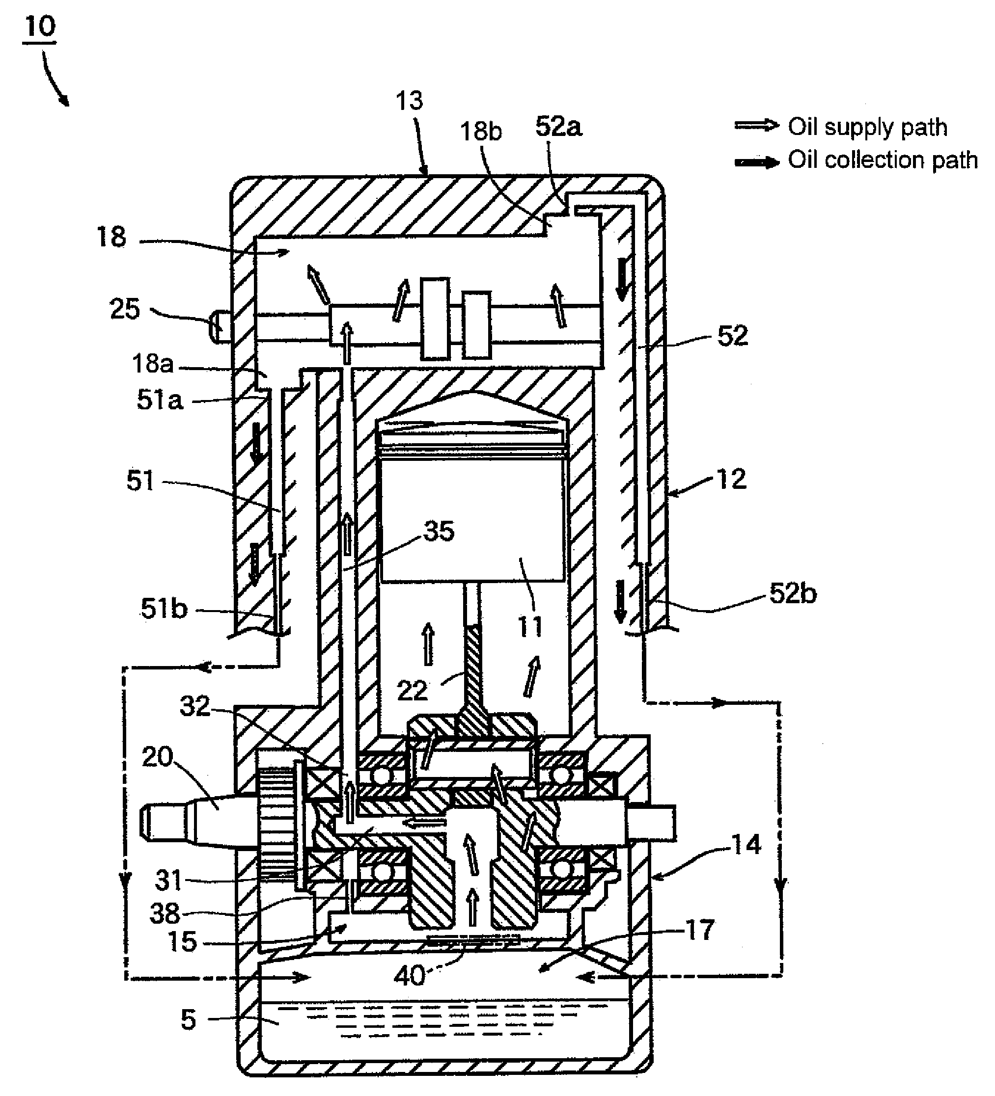
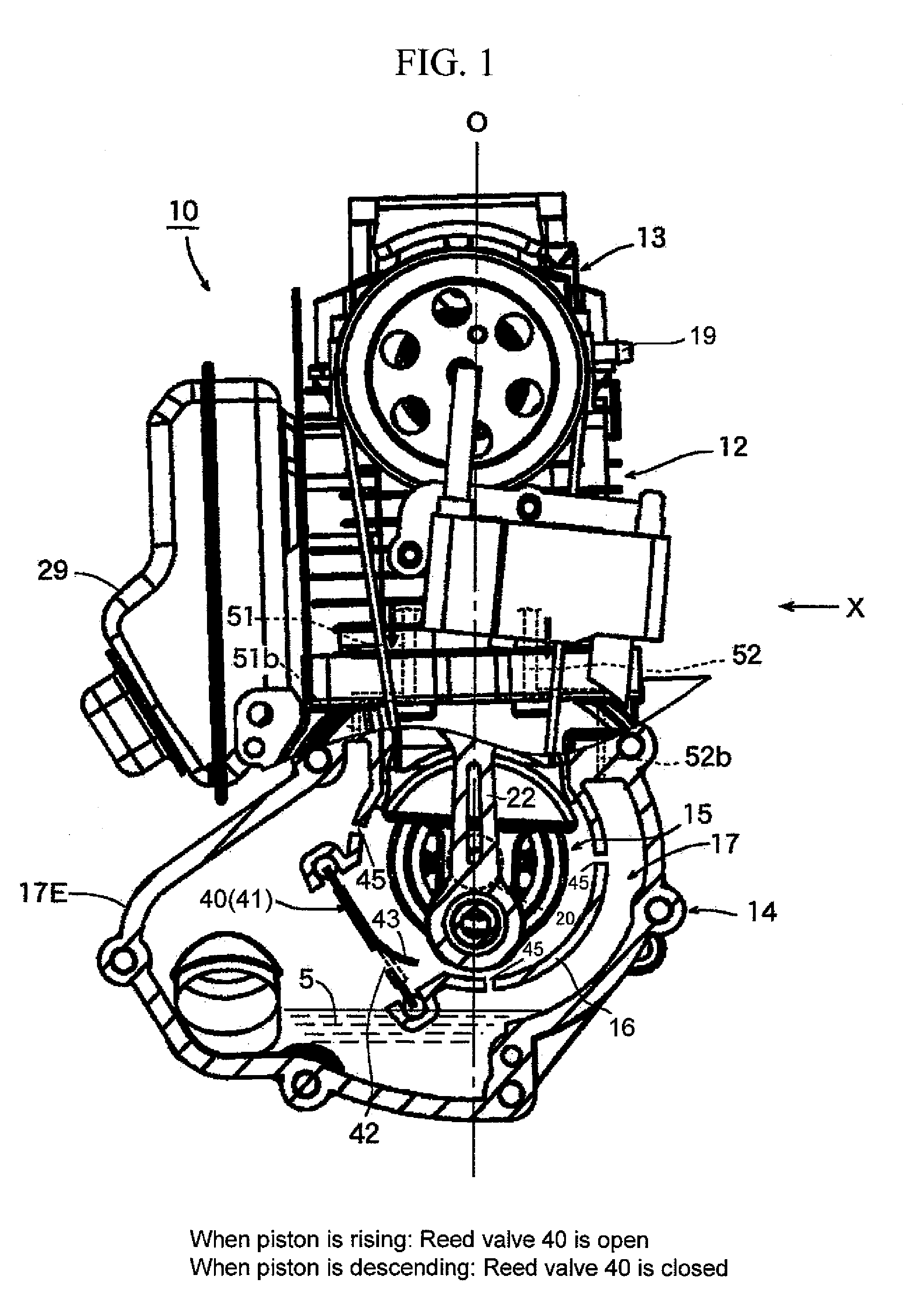
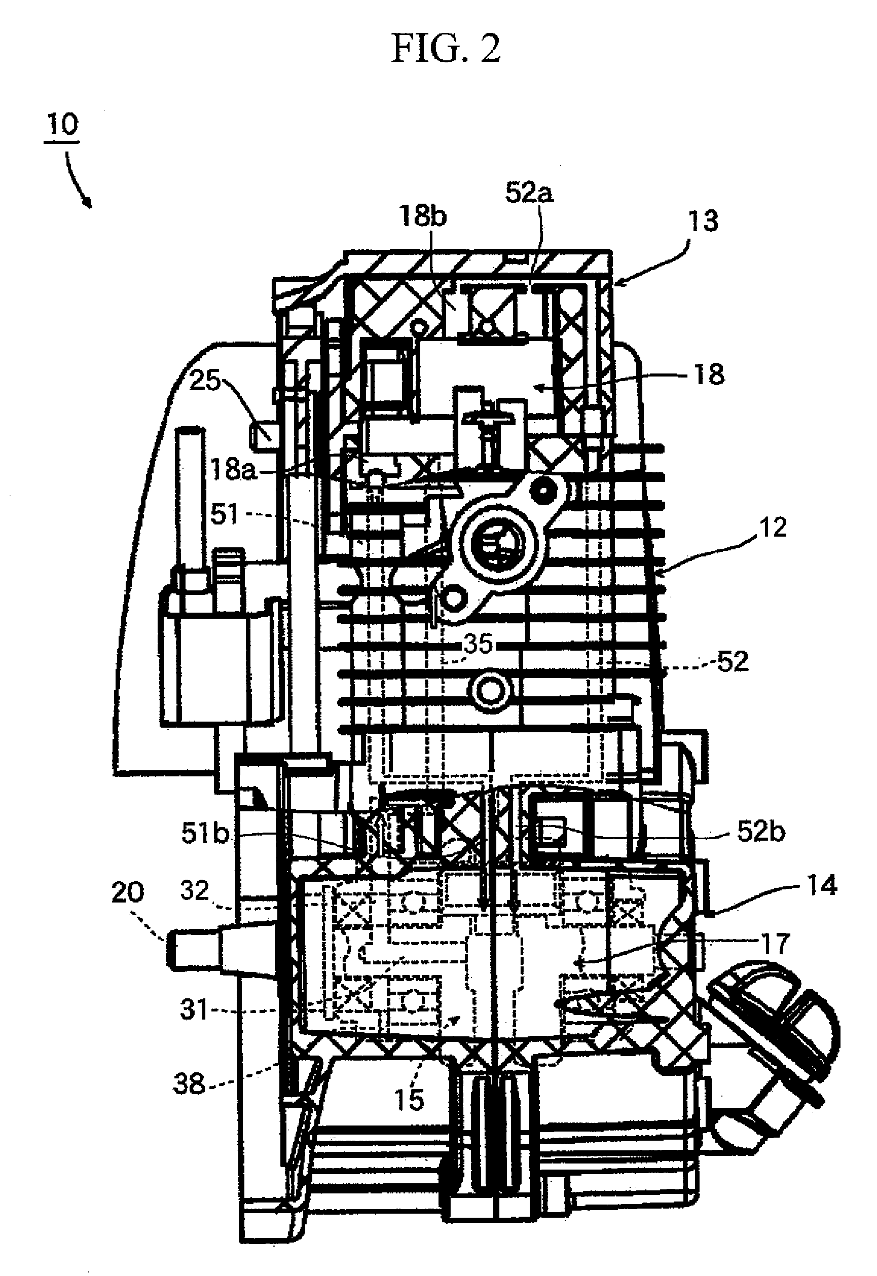
[0037]FIG. 1 is a partially cutaway front view of an overhead cam type four-stroke internal combustion engine to which an embodiment of a lubrication device according to the present invention is applied. FIG. 2 is a partially cutaway side view as viewed in the direction of arrow X in FIG. 1.

[0038]In FIGS. 3 and 4, which are schematic views of FIGS. 1 and 2, respectively, the outlined white arrows indicate the oil supply path, whereas the arrows with hatching indicate the oil collection path.

[0039]The engine 10 in FIG. 1 is an overhead earn type four-stroke internal combustion engine with a displacement of approximately 30 cc that is suitable for use as a power source for a portable work machine such as a brush cutter, a chain saw, etc. The engine 10 comprises: a cylinder portion 12 into which a piston 11 is inserted; an upper chamber defining portion 13 provided above the cylinder portion 1...


PUM


Abstract

There is provided a four-stroke internal combustion engine lubrication device that is capable of appropriately lubricating various parts regardless of engine orientation, of improving the capability for collecting excess oil within a valve chamber or the like and the capability for supplying oil to the various parts, and of reliably preventing oil leakage from a breather port provided in the valve chamber. It comprises: a reed valve (40) that allows oil flow from an oil chamber (17) into a crankcase (15) but prevents oil flow from the crankcase (15) to the oil chamber (17); an oil supply passage (35) for supplying oil from the crankcase (15) to a valve chamber (18); and a plurality of independent oil collection passages (51, 52) with differing inlet/outlet positions and for collecting in the oil chamber (17) the excess oil in the valve chamber (18). The dimensions of the various parts are so designed as to constantly maintain the oil chamber (17) under negative pressure during operation. The excess oil within the crankcase (15) is returned to the oil chamber (17) utilizing the negative pressure of the oil chamber (17).

Description

BACKGROUND INFORMATION[0001]The present invention relates to a lubrication device for a four-stroke internal combustion engine that is suitable for use as a power source of a portable work machine such as a brush cutter, a chain saw, etc., and more specifically to a four-stroke internal combustion engine lubrication device that is so arranged as to be capable of appropriately lubricating various parts regardless of the orientation of the work machine (engine), of improving the capability for collecting excess oil within a valve chamber, etc., and the capability for supplying oil to the various parts, and of reliably preventing oil leakage from a breather port (blow-by gas discharge port) provided in the valve chamber.[0002]JP Patent Publication (Kokai) No. 2002-188423 A (“Patent Document 1”), incorporated by reference herein, discusses four-stroke internal combustion engines that are suitable for use as power sources of portable work machines such as brush cutters, chain saws, etc.,...

Claims


Application Information

Patent Timeline
Patent Type & Authority Applications(United States)
IPC IPC(8): F01M1/02
CPCF01M1/04F01M11/0004F01M1/06
Inventor SAITOU, SHINICHIOHTSUBO, TOMOHIRO
Owner YAMABIKO CORP
Why Eureka
Try Eureka