Early warning device with passive indicator lamps and method

A passive indicator light and early warning device technology, applied in the direction of signal devices, etc., can solve the problems of driver interference, damage to the original car structure, and inability to restore, and achieve the effect of reducing the possibility of misoperation, ensuring driving safety, and simple installation.

Pending Publication Date: 2018-08-03
深圳市保途者科技有限公司
View PDF0 Cites 0 Cited by
  • Summary
  • Abstract
  • Description
  • Claims
  • Application Information

AI Technical Summary

Problems solved by technology

For this reason, the main purpose of the present invention is to provide an early warning device and method with a passive indicator light, aiming to solve the problem that the installation of the existing automobile early warning device will cause damage to the original car structure and cannot be restored, and the problem that the position cannot be moved and It cannot effectively transmit more accurate information to the driver, and sudden movements will cause unnecessary interference to the driver

Method used


Image

  • Early warning device with passive indicator lamps and method
  • Early warning device with passive indicator lamps and method

Examples


Embodiment 1

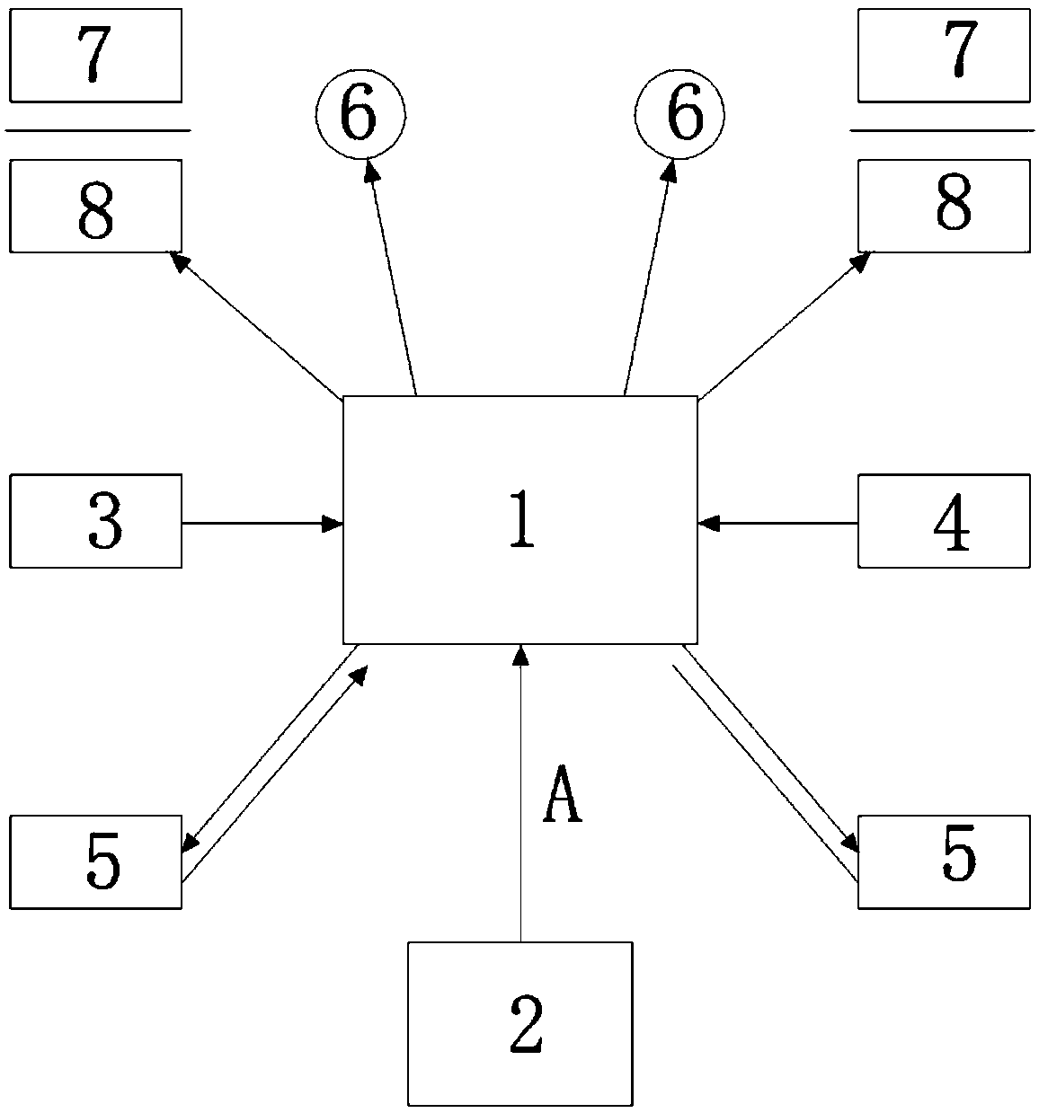
[0027] Such as figure 1 As shown, an early warning device with a passive indicator light includes a main logic control unit 1 connected to the vehicle control circuit 2 through a CAN bus A, and a signal acquisition unit and an indicating unit connected to the main logic control unit 1 respectively, the signal The acquisition unit includes a sound sensor 3, a light sensor 4 and a two-way radar 5, and the indicating unit includes two buzzers 6 and two passive indicator lights 7, and the passive indicator lights 7 are connected to the main unit through an inductive coupling device 8 A logic control unit 1, the inductive coupling device 8 includes an independent input terminal and an output terminal, the input terminal is connected to the main logic control unit 1, and the output terminal is connected to the passive indicator light 7, and the main logic control unit 1 includes a signal processing module, The input end of the signal processing module is connected to the vehicle con...

Embodiment 2

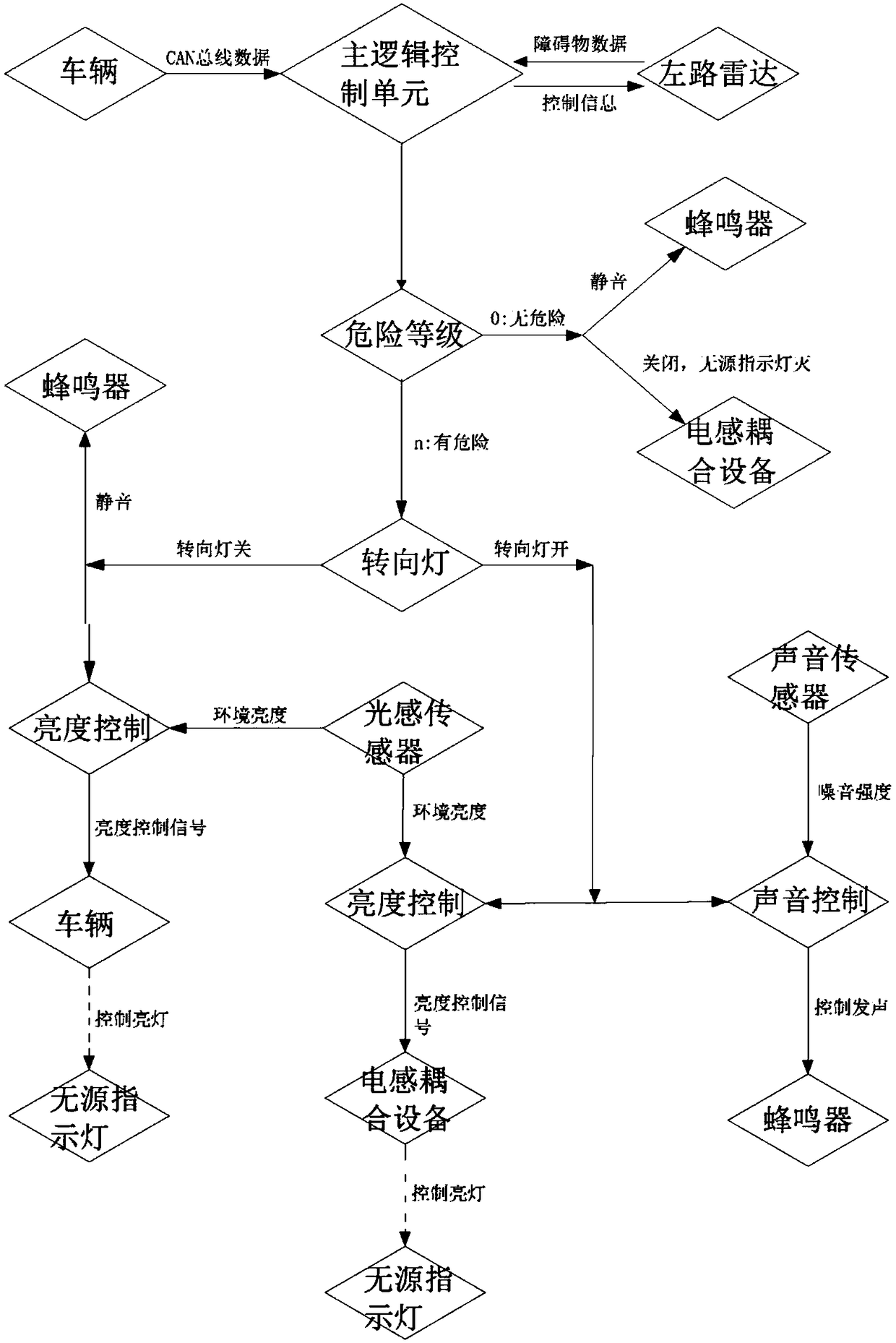
[0031] Such as figure 2 As shown, a control method of the aforementioned early warning device, the dangerous early warning steps on the left side are:

[0032] The main logic control unit reads the vehicle running data and the left radar data on the CAN bus in real time, and judges whether the set threshold is exceeded: if the data does not exceed the threshold, there will be no output, and the left buzzer and left passive indicator light will have no indication; if the data If the threshold is exceeded, the following processing will be performed according to the state of the read turn signal: if the turn signal is off, a signal will be output to the inductive coupling device to indicate the left passive indicator light; if the turn signal is on, a signal will be sent to the inductive coupling device, Make the left passive indicator light indicate and at the same time send a signal to the left buzzer to make the left buzzer give an indication.

[0033] The signal sent to the...


PUM


Abstract

The invention relates to an early warning device with passive indicator lamps. The early warning device comprises a main logic control unit, a signal acquisition unit and an indication unit, wherein the main logic control unit is connected with a vehicle control circuit through a CAN bus, and the signal acquisition unit and the indication unit are correspondingly connected with the main logic control unit. The indication unit comprises two buzzers and two passive indicator lamps, wherein the passive indicator lamps are connected with the main logic control unit through an inductive coupling device, and the inductive coupling device comprises an independent input end and an independent output end. The input end is connected with the main logic control unit, and the output end is connected with the passive indicator lamp. The invention further discloses an early warning method of the early warning device with the passive indicator lamp. The early warning device with the passive indicatorlamps and the method have the advantages of simple installation, no damage, and accurate indication.

Description

technical field [0001] The invention relates to the technical field of automobile safety assistance, in particular to an early warning device and method with a passive indicator light. Background technique [0002] In the existing technology, the indicator lamp products in the automotive field are mainly used for car driving safety assistance functions, such as lane change assist (LCA), blind spot warning (BSD), line pressure warning (LDW), forward collision warning (FCW), etc. . There are two ways to place an indicator light warning. [0003] One is to add an indicator light on the glass lens of the exterior rearview mirror. At present, the indicator light is mainly installed by replacing the lens or secondary processing on the original car lens. Replacing lenses will reduce the quality of the original car lenses, especially for mid-to-high-end models, and the high-quality lenses of the original car will be wasted. However, secondary processing on the original car lens ...

Claims


Application Information

Patent Timeline
Patent Type & Authority Applications(China)
IPC IPC(8): B60Q9/00
CPCB60Q9/008
Inventor 张开岭苏荣华
Owner 深圳市保途者科技有限公司
Why Eureka
Try Eureka