Controller of leg type moving robot

a robot and control device technology, applied in the direction of electric programme control, program control, instruments, etc., can solve the problems of increasing the discrepancy between the reaction force of the desired object and the reaction force of the actual object, affecting and frequently disagreeing with the predicted environmental conditions. to achieve the effect of ensuring the stability of the robo

Inactive Publication Date: 2010-12-07
HONDA MOTOR CO LTD
View PDF20 Cites 4 Cited by
  • Summary
  • Abstract
  • Description
  • Claims
  • Application Information

AI Technical Summary

Benefits of technology

[0020]According to the first aspect of the invention described above, the desired action force between the robot and the object is determined such that the motion state amount of the object on the object dynamic model follows the desired motion state amount (e.g., the desired velocity of the object) determined on the basis of the moving plan of the object (the schedule showing the timings and methods for moving the object), and the determined desired action force is supplied to the object dynamic model. The force acting between the robot and the object includes a force acting on the object from the robot and a force acting onto the robot from the object, but they differ only in sign (the direction of force), so that the desired value of either of the forces may be defined as the desired action force between the robot and the object. And, the desired moving position determining means determines the desired moving position of the object while correcting the motion state amount of the object on the object dynamic model on the basis of a motion manipulated variable determined such that the difference between the actual moving position and the desired moving position approximates zero. This makes it possible to determine the desired moving position of the object and the desired action force between the robot and the object by using the dynamic model while minimizing the discrepancy between the motion state of the object on the object dynamic model and the motion state of the actual object. Furthermore, the present invention controls an operation of the robot on the basis of the desired position of the object and the desired action force between the robot and the object, thus making it possible to cause the robot to perform the operation of moving the object without causing the robot to perform an unreasonable operation, which may lead to a sudden change of a behavior of the robot. As a result, it is possible to cause the robot to perform the operation of moving the object while securing the stability of the robot.
[0251]As described above, the present invention is useful as it is capable of causing a robot, such as a bipedal mobile robot, to smoothly perform an operation of moving an object, while securing the stability of the robot at the same time.

Problems solved by technology

However, actual environmental conditions frequently disagree with predicted environmental conditions.
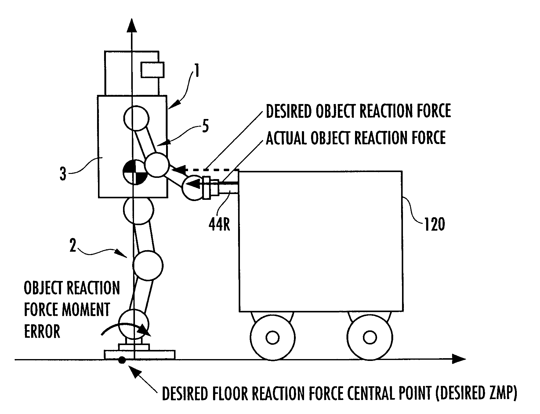
As a result, even when the operation of the robot is controlled so as to satisfy the dynamic balance condition of the robot on the basis of the desired object reaction force, the discrepancy between the desired object reaction force and the actual object reaction force prevents the dynamic balance condition of the actual robot from being satisfied, thus impairing the stability of the robot.
However, in a situation wherein a discrepancy takes place between a desired object reaction force and an actual object reaction force, another discrepancy generally takes place between a moving position of an object based on a moving plan (i.e., a desired moving position of an object) and an actual moving position of the object.
For this reason, as with the aforesaid one in Patent Document 1, even if the position of the center-of-gravity of the robot or the desired value of the floor reaction force is corrected so as to cancel the difference between the desired object reaction force and the actual object reaction force, the discrepancy between the desired object reaction force and the actual object reaction force excessively increases or the discrepancy frequently occurs in some cases.
In such a case, there has been a danger in that an excessive behavior change of the robot takes place, thus making it difficult to cause the robot to successively perform the operation of moving the object while continuously maintaining the stability of the robot.
However, if, for example, the actual object reaction force suddenly changes and if the desired object reaction force is suddenly changed in response thereto, then the robot develops an excessive behavior change, which could easily impair the stability of the robot.
In this case, the desired object reaction force could be slowly changed in response to the change in the actual object reaction force; however, doing so would cause a delay in the change of the desired object reaction force in response to the change of the actual object reaction force.
This would prevent the dynamic stability of the robot from being promptly secured, resulting in impaired stability of the robot.

Method used


Image

  • Controller of leg type moving robot
  • Controller of leg type moving robot
  • Controller of leg type moving robot

Examples


first embodiment

[0058]The following will explain in detail a gait generator 100 according to a first embodiment of the present invention. FIG. 5 to FIG. 7 are flowcharts showing the processing by the gait generator 100. The first embodiment is an embodiment of the first aspect, the third aspect, and the fourth aspect of the present invention.

[0059]The gait generator 100 sequentially carries out the processing shown in the flowcharts of FIG. 5 to FIG. 7 at a predetermined calculation processing cycle.

[0060]First, in S01, a moving plan for an object 120 is determined. The moving plan to be determined here includes at least a moving plan for the object 120 for a predetermined future period (for a plurality of steps of the robot 1) from the current time. The moving plan is decided basically according to a moving requirement of the object 120 (a design requirement on a method and timing for moving the object 120), and it is constituted of a position / posture trajectory (a time series of position and post...

second embodiment

[0230]A second embodiment of the present invention will now be explained with reference to FIG. 20. In the explanation of the second embodiment, the like components or the like functional portions as those in the first embodiment will use the like reference numerals as those in the first embodiment, and the explanation thereof will be omitted. The second embodiment is an embodiment of the first to the fourth aspects of the present invention.

[0231]The second embodiment differs from the first embodiment only in the processing for correcting a moving plan in S01 of FIG. 5. This will be explained below. A situation in which the difference between an actual object motion trajectory and a desired object motion trajectory based on a moving plan increases occurs if a relatively large change takes place in a disturbance force other than a force acting on the robot 1 of a force acting on an actual object 120.

[0232]Hence, according to the second embodiment, instead of correcting a moving plan ...

third embodiment

[0238]A third embodiment of the present invention will now be explained with reference to FIG. 21 to FIG. 23. In the explanation of the third embodiment, the like components or the like functional portions as those in the first embodiment will use the like reference numerals as those in the first embodiment, and the explanation thereof will be omitted. The third embodiment is an embodiment of the first aspect, the third aspect, and the fourth aspect of the invention.

[0239]FIG. 21 is a flowchart showing the processing of a part associated with the processing shown in FIG. 5 related to the first embodiment in the processing by a gait generator 100 in the third embodiment. As shown in FIG. 21, the third embodiment differs from the first embodiment only in the processing carried out when a determination result of S19 is NO.

[0240]More specifically, when a determination result of S19 is NO, a desired object reaction force trajectory has been corrected in the first embodiment; the third em...


PUM


Abstract

A controller of a leg type moving robot determines an action force to be input to an object dynamic model 2 such that a motion state amount (object model velocity) of the object dynamic model 2 follows a desired motion state amount based on a moving plan of an object, and also determines a manipulated variable of the motion state amount (object model velocity) of the object dynamic model 2 such that the difference between an actual object position and a desired object position approximates zero, and then inputs the determined action force and manipulated variable to the object dynamic model 2 to sequentially determine the desired object position. Further, a desired object reaction force to a robot from the object is determined from the determined reaction force. This arrangement causes the robot to perform an operation of moving an object while securing stability of the robot by determining the desired motion of the object and the desired value of an action force between the object and the robot while minimizing the difference between a motion state of the object on the object dynamic model and an actual motion state.

Description

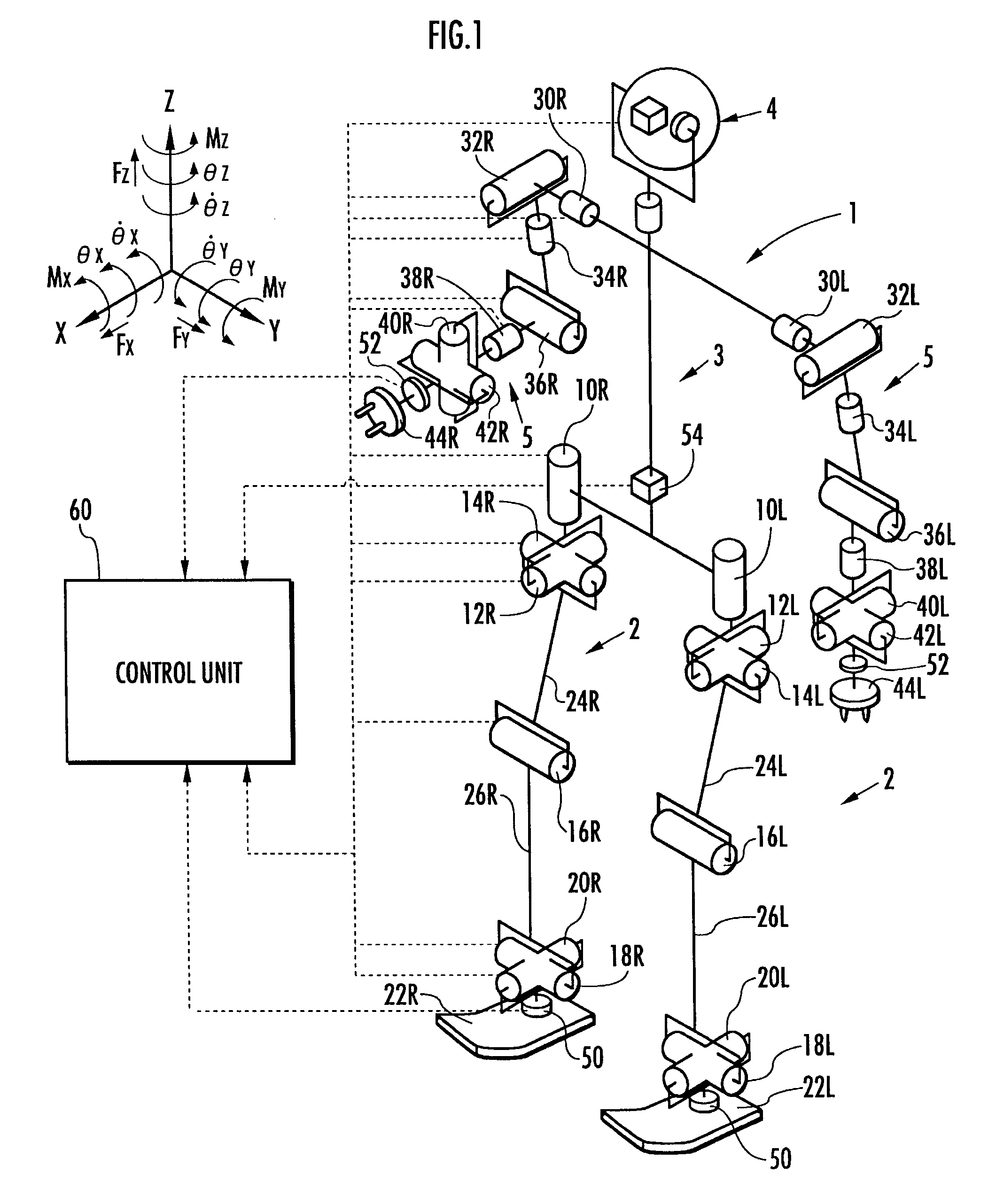
TECHNICAL FIELD[0001]The present invention relates to a controller for causing a leg type moving robot to carry out an operation of moving an object.BACKGROUND ART[0002]When causing a leg type moving robot, such as a bipedal moving robot, to perform an operation of, for example, moving a certain object by pushing, the robot is subjected not only to a floor reaction force from a floor with which a distal portion of a leg thereof is in contact but also to a reaction force from the object. The reaction force received by the robot from the object is referred to as an object reaction force in the present description.[0003]As a technology for generating a gait of a robot or controlling an operation thereof in a state wherein an object reaction force is acting on a leg type moving robot, there has been known a technology disclosed in, for example, Japanese Patent Laid-Open No. H10-230485 by the inventor of the present application (hereinafter referred to as Patent Document 1). According to...

Claims


Application Information

Patent Timeline
Patent Type & Authority Patents(United States)
IPC IPC(8): G05B19/00
CPCB62D57/032B25J13/00B25J5/00
Inventor HASEGAWA, TADAAKI
Owner HONDA MOTOR CO LTD
Why Eureka
Try Eureka