
Method for fast access to flash-memory media

a flash-memory media and fast technology, applied in the direction of memory adressing/allocation/relocation, instruments, error detection/correction, etc., can solve the problem of limited size and extent of the structure used to describe deferred copy operations, and achieve the effect of reducing the number of data copy operations and fast write access to flash-memory media

Active Publication Date: 2010-12-07
MICROCHIP TECH INC
View PDF10 Cites 13 Cited by
  • Summary
  • Abstract
  • Description
  • Claims
  • Application Information

AI Technical Summary

Benefits of technology

The patent describes a system and method for reducing the number of data copy operations when transferring data to flash-memory devices. This is achieved by managing non-volatile memory devices with a memory controller that minimizes unnecessary operations and memory-intensive data structures. The data may be maintained contiguously, reducing the storage requirements of lookup tables. The system also allows for re-write operations to partially complete by skipping the final copy phase and maintaining a descriptor of the current state of the re-write operation. The cache may contain descriptors for multiple blocks, and the system may reclaim resources at will. The technical effects of the patent include faster write access to flash-memory media with reduced data copy operations and improved performance and fault recovery.

Problems solved by technology

The size and extent of structures used to describe the deferred copy operations may be limited, in turn minimizing RAM requirements.
Reclamation may be necessary due to resource constraints such as limited storage for sector descriptors or a limited number of unbound blocks.

Method used


Image

  • Method for fast access to flash-memory media
  • Method for fast access to flash-memory media
  • Method for fast access to flash-memory media

Examples


Embodiment Construction

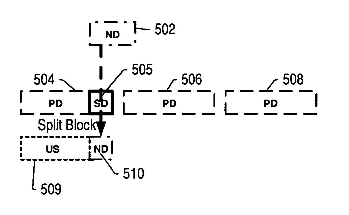
[0029]As referenced herein, the terms “flash-memory” and “flash-media” are used interchangeably to mean a special type of electrically erasable programmable read-only memory (EEPROM) that can be erased and reprogrammed in minimum erasable-units, referred to herein as ‘blocks’, instead of one byte at a time. In addition, each block may be organized into subunits called ‘sectors’, where a sector may represent a minimum data size for data stored on a given flash-memory device. While preferred embodiments are described in detail for flash-memory devices organized into blocks and sectors, alternate embodiments featuring other types of non-volatile memory devices organized into minimum erasable-units and subunits are possible and are contemplated. Therefore, it should be understood that “block”, specifically, is used interchangeably with what is referred to generally as “erasable unit” or “EU” for short. As also used herein, “writing a sector” or “writing a subunit” means writing data to ...


PUM


Abstract

In one embodiment, the invention comprises a flash-media controller used for writing new data from an external system to a local flash-memory device. The newly written data may replace old data previously written to the flash-memory device, and may be written directly to unused locations within the flash-memory device. The flash-media controller may comprise a table of block descriptors and sector descriptors used to track specified characteristics of each block and sector of the flash-memory device, thereby allowing for write sequences to non-contiguous sectors within a block. Accordingly, copy operations may be deferred under the expectation that they will eventually become unnecessary, thereby designating old data as having become stale. Once all data within a block has been designated as being stale, the block may be marked as unused and may be made available for subsequent write operations, thereby providing fast write access to the flash-memory device, and significantly reducing the number of required copy operations during data transfer to the flash-memory device.

Description

BACKGROUND OF THE INVENTION[0001]1. Field of the Invention[0002]This invention relates generally to the field of digital interface design and, more particularly, to digital storage interface design.[0003]2. Description of the Related Art[0004]In recent years the electronics marketplace has seen a proliferation of appliances and personal electronics devices that use solid-state memory. For example, traditional film cameras have been losing market share to digital cameras capable of recording images that may be directly downloaded to and stored on personal computers (PCs). The pictures recorded by digital cameras can easily be converted to common graphics file formats such as JPEG, GIF or BMP, and sent as e-mail attachments or posted on web pages and online photo albums. Many digital cameras are also capable of capturing short video clips in standard digital video formats, for example MPEG-2, which may also be directly downloaded and stored on PCs or notebook computers. Other devices ...

Claims


Application Information

Patent Timeline
Patent Type & Authority Patents(United States)
IPC IPC(8): G06F12/06
CPCG06F11/1435G06F12/0246
Inventor STEWART, GUY A.
Owner MICROCHIP TECH INC
Learn More