Emergency stop device of elevator
a technology of emergency stop and elevator, which is applied in the direction of elevator, transportation and packaging, etc., can solve the problems of increasing the impact of the car, the car has already become high, and it takes a while to generate the braking force, so as to reduce the braking distance a car travels
- Summary
- Abstract
- Description
- Claims
- Application Information
AI Technical Summary
Benefits of technology
Problems solved by technology
Method used
Image

Examples
embodiment 1
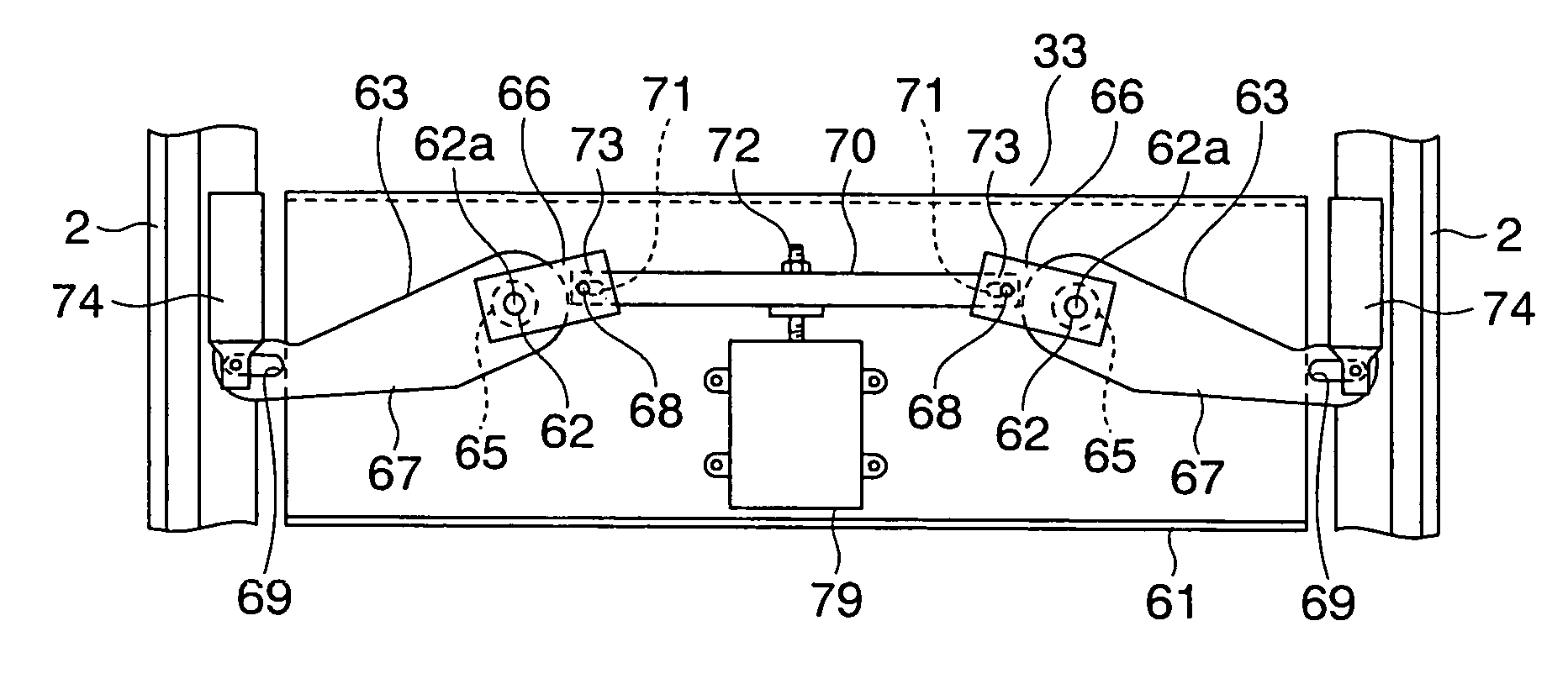
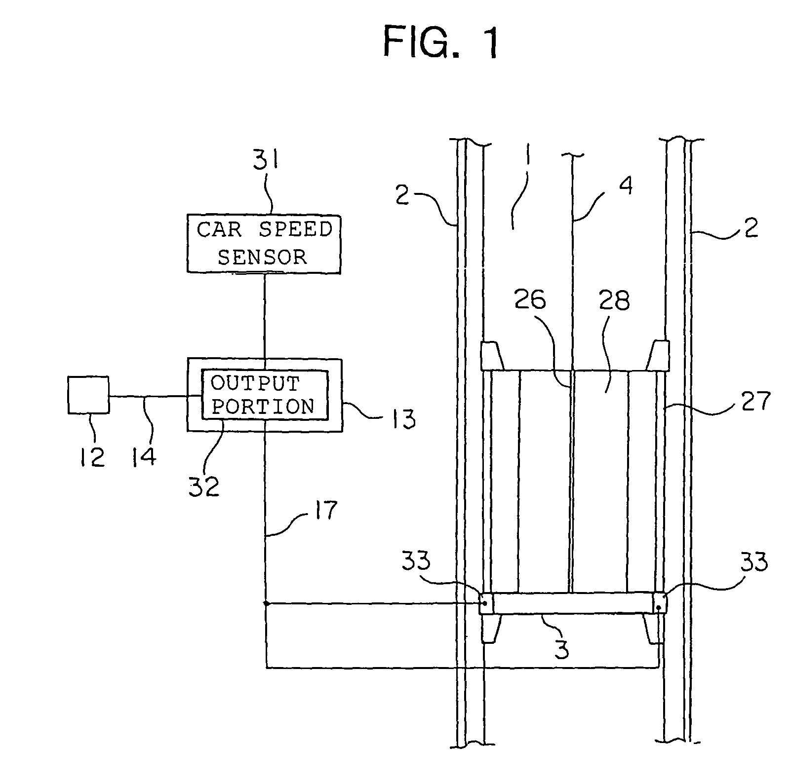
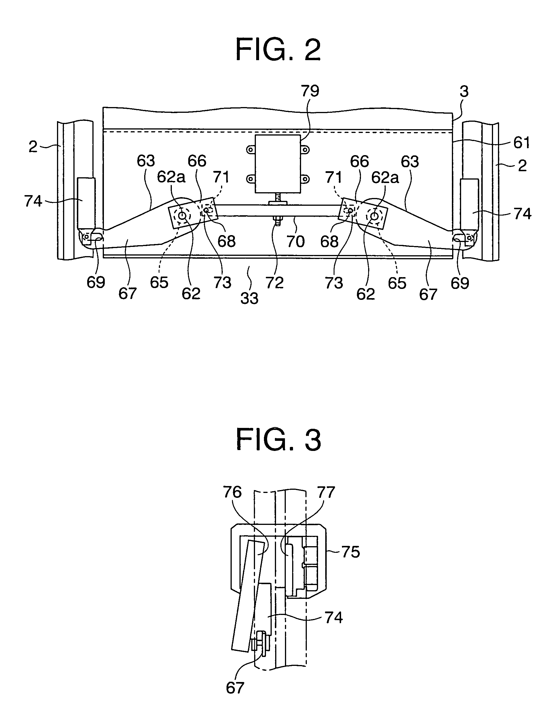
[0036]FIG. 1 is a schematic diagram showing an elevator apparatus according to Embodiment 1 of the present invention. Referring to the drawing, a pair of car guide rails 2 are disposed in a hoistway 1. A car 3 is raised and lowered in the hoistway 1 while being guided by the car guide rails 2. A hoisting machine (not shown) for raising and lowering the car 3 and a counterweight (not shown) is arranged at an upper end portion of the hoistway 1. Main ropes 4 are wound around a driving sheave of the hoisting machine. The car 3 and the counterweight are suspended in the hoistway 1 by the main ropes 4. The car 3 is mounted with a safety device 33 serving as braking means for preventing the car 3 from falling. The safety device 33 is arranged in a lower portion of the car 3. Braking is applied to the car 3 upon actuating the safety device 33.
[0037]The car 3 has a car main body 27 provided with a car entrance 26, and a car door 28 for opening and closing the car entrance 26. In the hoistwa...
embodiment 2
[0063]FIG. 11 is a front view showing a safety device for an elevator according to Embodiment 2 of the present invention. Further, FIG. 12 is a front view showing the safety device of FIG. 11 in an actuated state. Referring to the drawings, a pair of pivot levers 81, 82 are fixed to the respective pivot shafts 62. As shown in FIGS. 13, 14, one pivot lever, the pivot lever 81, includes the boss 65 and the arm portion 67 that are the same as those of Embodiment 1, and an extending portion 83 extending upwards from an end portion of the boss 65. Further, the other pivot lever, the pivot lever 82, includes the boss 65 and the arm portion 67 that are the same as those of Embodiment 1, and an extending portion 84 extending downwards from an end portion of the boss 65. The respective bosses 65 and arm portions 67 of the one and the other pivot levers 81, 82 are arranged symmetrically with respect to the center line of the emergency stop frame 61.
[0064]The projecting portion 68 is provided ...
embodiment 3
[0074]FIG. 17 is a schematic diagram showing an elevator apparatus according to Embodiment 3 of the present invention. In FIG. 17, a hoisting machine 101 serving as a driving device and a control panel 102 are provided in an upper portion within the hoistway 1. The control panel 102 is electrically connected to the hoisting machine 101 and controls the operation of the elevator. The hoisting machine 101 has a driving device main body 103 including a motor and a driving sheave 104 rotated by the driving device main body 103. A plurality of main ropes 4 are wrapped around the sheave 104. The hoisting machine 101 further includes a deflector sheave 105 around which each main rope 4 is wrapped, and a hoisting machine braking device (deceleration braking device) 106 for braking the rotation of the drive sheave 104 to decelerate the car 3. The car 3 and a counter weight 107 are suspended in the hoistway 1 by means of the main ropes 4. The car 3 and the counterweight 107 are raised and low...
PUM
 Abstract
Description
Claims
Application Information
 - R&D
- Intellectual Property
- Life Sciences
- Materials
- Tech Scout
- Unparalleled Data Quality
- Higher Quality Content
- 60% Fewer Hallucinations
Browse by: Latest US Patents, China's latest patents, Technical Efficacy Thesaurus, Application Domain, Technology Topic, Popular Technical Reports.
© 2025 PatSnap. All rights reserved.Legal|Privacy policy|Modern Slavery Act Transparency Statement|Sitemap|About US| Contact US: help@patsnap.com