Safety arrangement of an elevator having sensors limiting extent of elevator travel

a safety arrangement and elevator technology, applied in the direction of instruments, structural/machine measurement, hardware monitoring, etc., can solve the problems of difficult to achieve the effect of extending the shaft upwards or downwards, difficult to achieve the effect of being unviable, and often encountered in old buildings

Active Publication Date: 2010-12-14
KONE CORP
View PDF14 Cites 38 Cited by
  • Summary
  • Abstract
  • Description
  • Claims
  • Application Information

AI Technical Summary

Benefits of technology

[0027]The control unit can be implemented e.g. with a microcontroller, with a programmable logic circuit, with programmable logic or with relays. The control unit can also comprise at least two microcontrollers, or some other independently operating logic control, which operate independently irrespective of each other and additionally communicate with each other via a separate communication channel and thus monitor each other's operation in order to improve the safety of the control unit.
[0070]The control unit can also be fitted to switch to the person in the elevator shaft mode always afterwards in conjunction with an electrical power cut if also the backup drive, such as an accumulator, has ceased to supply operating electricity to the safety arrangement. In this case driving with the elevator is not possible before the serviceman visits the site to cancel the person in the elevator shaft mode. This prevents a hazardous situation, which could arise when a person moves into the elevator shaft after loss of electricity from the safety arrangement.
[0072]movement of the elevator car in the elevator shaft is prevented by controlling the car brake with the control unit and
[0100]The invention achieves at least one of the following advantages:
[0102]Since in the safety arrangement according to the invention the safety spaces of the elevator are monitored with a separate control unit, the signals to be monitored can be filtered using a software program in the control unit according to need. In this case the system is immune to short-term breaks in the contacts of the switches. When the operational disturbances of the elevator system caused by these short-term breaks decrease, the reliability and utilization rate of the elevator system improve.
[0103]The safety arrangement according to the invention requires very complex operating logic so that it is possible to ensure that the system detects all possible fault situations. The logic used must exclude all operating modes in which service drive is prohibited and permit those operating modes in which service drive is permitted. Furthermore the system must be able to infer malfunctioning of the sensors. In the safety arrangement according to the invention the monitoring of operation is performed centrally in an electrical safety device, which simplifies the implementation compared to a solution implemented with different components. At the same time the total amount of components in the system decreases and the reliability of the system improves.

Problems solved by technology

When modernizing the elevators of old buildings problems are often encountered because the safety regulations have changed over the years and the headrooms and bottom clearances in the elevator shaft above and below the car in the elevator shaft are not large enough to meet the requirements of modern safety regulations.
Extending the shaft upwards or downwards is in most cases impossible in terms of construction engineering or at least so expensive and difficult that it is not viable.
In this case there is no longer adequate safety space for personnel protection above and below the elevator car for a serviceman working in the elevator shaft or on the roof of the elevator car.

Method used


Image

  • Safety arrangement of an elevator having sensors limiting extent of elevator travel
  • Safety arrangement of an elevator having sensors limiting extent of elevator travel
  • Safety arrangement of an elevator having sensors limiting extent of elevator travel

Examples


Embodiment Construction

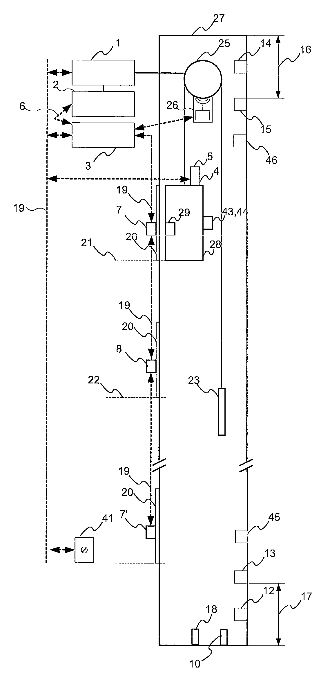
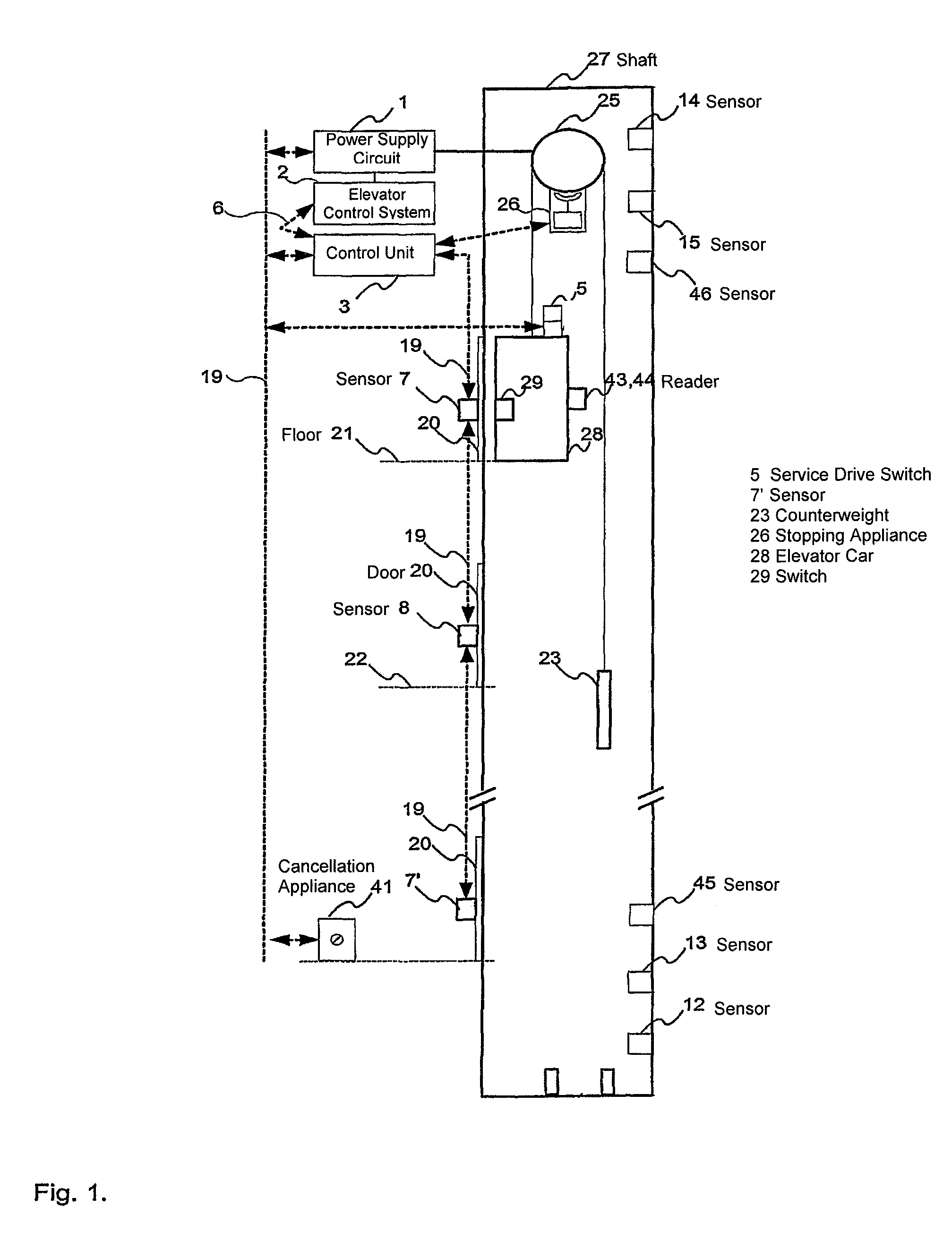
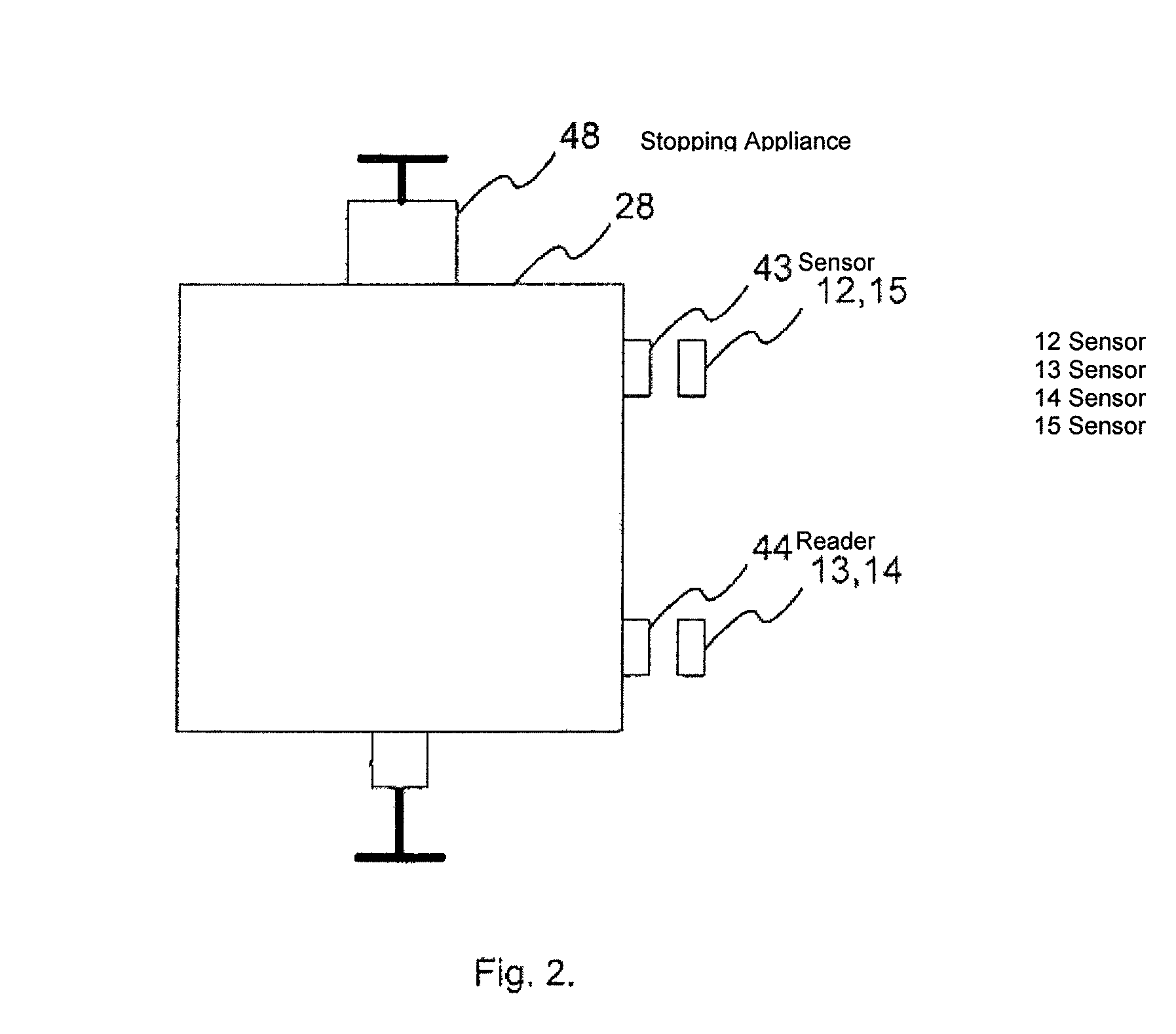
[0114]FIG. 1 presents one elevator, in which the safety arrangement according to the invention is applied. The elevator car 28 is fitted to move in the elevator shaft 27 from floor to floor 21, 22. This elevator system according to this invention also contains a counterweight 23, but the elevator system according to the invention can also be one without counterweight. The elevator motor 25 is situated in the elevator shaft, but it can also be situated in a machine room.

[0115]In one embodiment of the invention the end limits of movement of the elevator car in the elevator shaft are set by the end-limit sensors 12, 13, 14, 15, 45, 46. During normal drive the elevator car travels between the end limits defined by the end-limit switches 12, 14. After the serviceman has moved into the elevator shaft the control unit 3 switches at first into the person in the elevator shaft mode. In this case the control unit prevents driving with the elevator by controlling the mechanical stopping applia...


PUM


Abstract

The invention relates to a safety arrangement of an elevator and a method for implementing safety spaces in an elevator shaft. The elevator has an elevator control system, an elevator motor, a power supply circuit of the elevator motor, and at least one mechanical stopping appliance for preventing movement of the elevator car in the elevator shaft. In the method according to the invention information is read with the control unit from the sensors that measure the position of the landing door of the elevator and possibly information is read from the sensors that measure the position of the door of the elevator car. If it is detected that more landing doors than the door of the elevator car are open, the control unit is switched to the person in the elevator shaft mode and information about the person in the elevator shaft mode is sent with the control unit to the elevator control system.

Description

[0001]This application is a Continuation of copending PCT International Application No. PCT / FI2007 / 000290 filed on Dec. 13, 2007, which designated the United States, and on which priority is claimed under 35 U.S.C. §120. This application also claims priority under 35U.S.C. §119(a) on Patent Application Nos. 20070006, 20070469 and 20070486 filed in Finland on Jan. 3, 2007, Jun. 13, 2007 and Jun. 19, 2007. The entire contents of each of the above documents is hereby incorporated by reference.FIELD OF THE INVENTION[0002]The present invention relates to a safety arrangement of an elevator.PRIOR ART[0003]When modernizing the elevators of old buildings problems are often encountered because the safety regulations have changed over the years and the headrooms and bottom clearances in the elevator shaft above and below the car in the elevator shaft are not large enough to meet the requirements of modern safety regulations. Extending the shaft upwards or downwards is in most cases impossible...

Claims


Application Information

Patent Timeline
Patent Type & Authority Patents(United States)
IPC IPC(8): B66B1/34
CPCB66B13/22B66B5/0031B66B5/0056B66B5/0068
Inventor KETONEN, ARIKATTAINEN, ARI
Owner KONE CORP
Why Eureka
Try Eureka