Controller for controlling robot body with power-off brake

a technology of robot body and control lever, which is applied in the direction of electric programme control, dynamo-electric converter control, program control, etc., can solve the problems of increasing affecting the operation of the robot body, and the vertical rotation of the arm by the joint falling by gravity, so as to reduce the high-speed movement of the robot body and increase the complexity of the robot body structur

Inactive Publication Date: 2010-12-14
DENSO WAVE INC
View PDF5 Cites 31 Cited by
  • Summary
  • Abstract
  • Description
  • Claims
  • Application Information

AI Technical Summary

Benefits of technology

[0016]In view of the background, an object of an aspect of the present invention is to provide controllers and program products for controlling a robot body in which a servomotor and a power-off brake therefor are installed; these controller and program products are capable of, when the power-off brake is released, reducing high-speed movement of the robot body without increasing complexity of the structure of the robot body.

Problems solved by technology

In an articulated robot, this may result that an arm vertically rotatable by a joint falls by gravity.
In articulated robots or the like, when a power-off brake is released, a vertically swingable arm may fall by gravity, or an arm may rise due to air unbalance.
However, when the power-off brake is released with the dynamic brake failing, a link of the robot body may start to move at a high speed simultaneously with the release of the power-off brake.
However, the structure of the mechanism required to cause the ratchet to be engaged with the vertically movable arm of the robot body may increase complexity of the structure of the robot body.

Method used


Image

  • Controller for controlling robot body with power-off brake
  • Controller for controlling robot body with power-off brake
  • Controller for controlling robot body with power-off brake

Examples


first embodiment

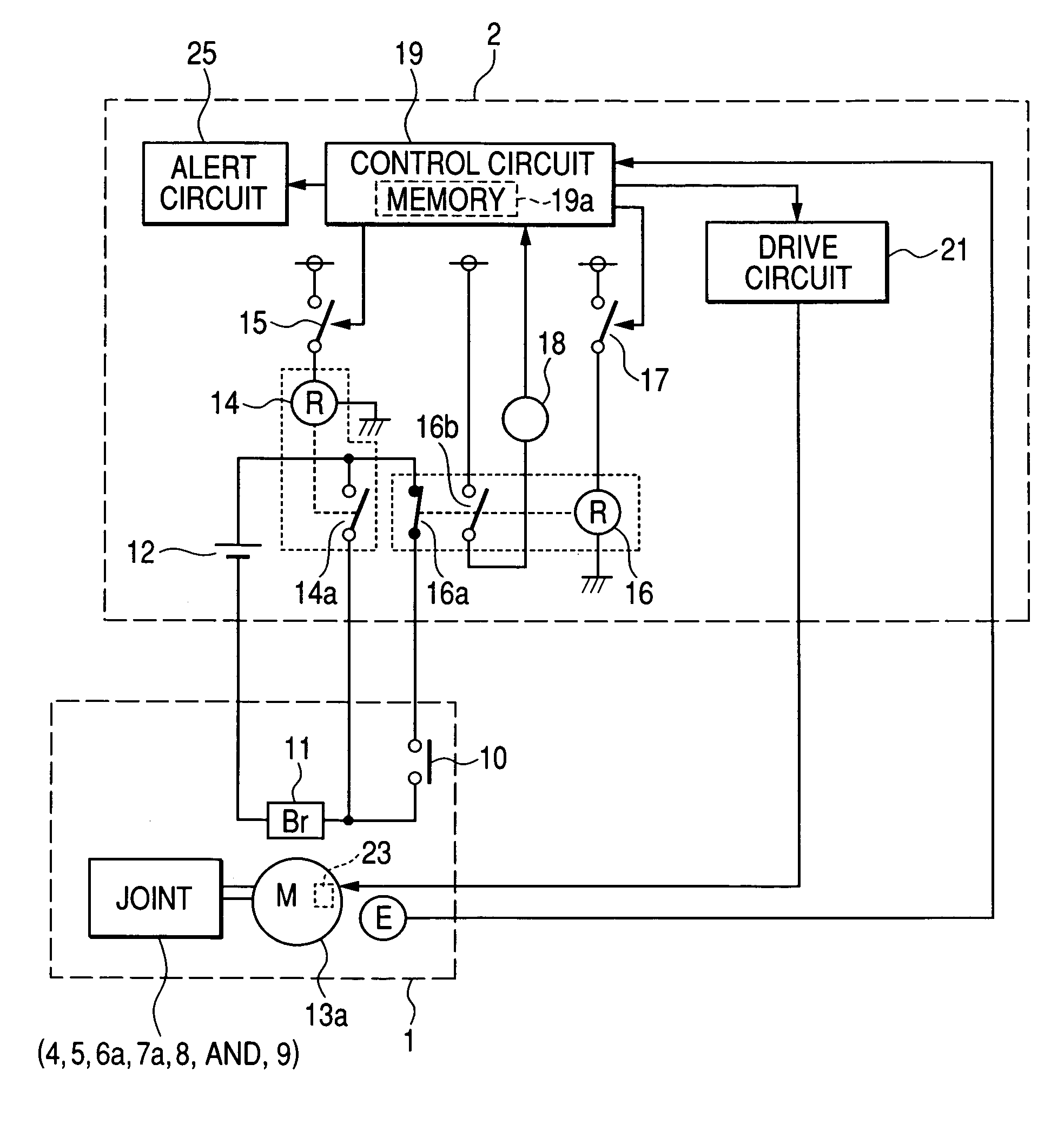
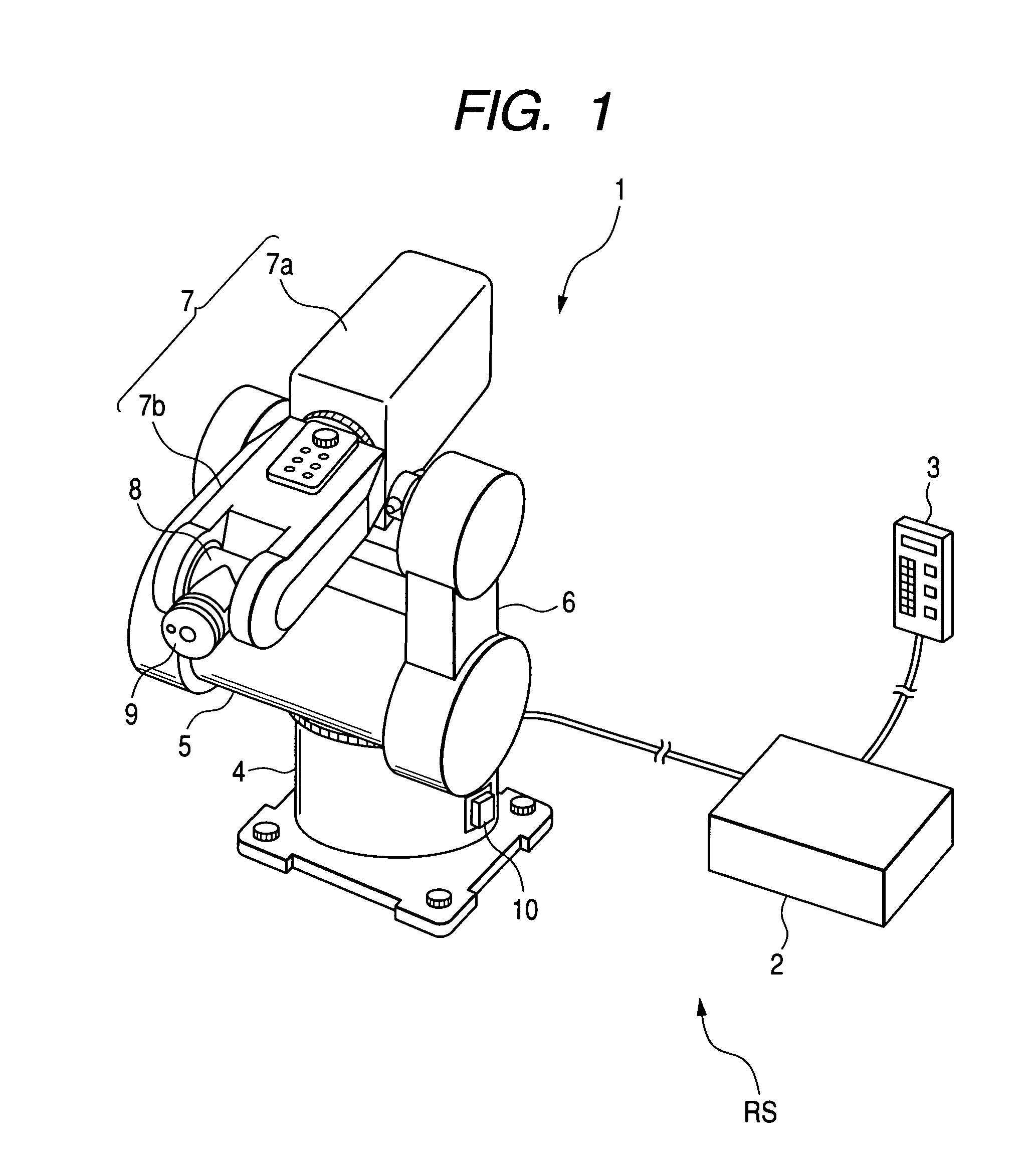
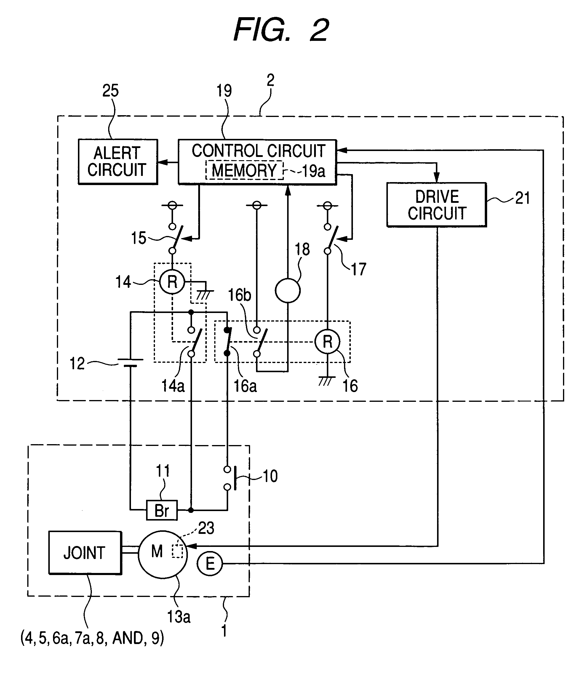
[0031]Referring to FIGS. 1 to 3, there is illustrated an example of the overall structure of a robot system RS according to a first embodiment of the present invention.

[0032]The robot system RS is equipped with a robot body 1, a controller 2 electrically connected thereto via a cable and designed to control the robot body 1, and a teaching pendant 3 as a teaching box for the controller 2.

[0033]The robot body 1 is designed as, for example, an articulated robot body.

[0034]The robot body 1 consists of a substantially cylindrical base 4 mounted on a horizontal installation surface, such as a flooring of a factory. The robot body 1 consists of a substantially cylindrical shoulder joint 5 mounted on the base 4 such that the center axial direction of the shoulder joint 5 is orthogonal to the center axial direction of the base 4.

[0035]The shoulder joint 5 is configured to be horizontally rotatable on the base 4 about a center axis (motion axis) of the base 4. Specifically, the base 4 serves...

second embodiment

[0132]A robot system according to a second embodiment of the present invention will be described hereinafter. The robot system of the second embodiment has substantially the same structure as that of the robot system RS of the first embodiment except for some differences described hereinafter. For this reason, like reference characters are assigned to like parts in the robot systems according to the first and second embodiments so that descriptions of the parts of the robot system of the second embodiment will be omitted or simplified.

[0133]Referring to FIG. 4, a controller 2A of the robot system according to the second embodiment is further provided with a current sensor 20 as an example of a detector for detecting an on operation of the brake-release switch 10.

[0134]In the first embodiment, the control circuit 19 is configured to compute an actual motion speed of each of the joints 5 and 6a (an actual speed of each of the servomotors 13a) based on the pulse signal sent from the ro...


PUM


Abstract

In a controller, a first switch unit establishes electrical connection between a power-off brake and a power source when a servomotor is energized. The electrical connection causes the power-off brake to be released. A second switch unit is provided between the power-off brake and the power source. The second switch unit establishes electrical connection between the power-off brake and the power source upon being manually operated during the servomotor being deenergized. A calculating unit calculates a driving speed of the joint by the servomotor. A determining unit determines whether the calculated driving speed of the joint is greater than a predetermined threshold speed. An interrupting unit interrupts a supply of electrical power from the power source to the power-off brake through the electrical connection established by the second switch unit when it is determined that the calculated driving speed of the joint is greater than the predetermined threshold speed.

Description

CROSS REFERENCE TO RELATED APPLICATIONS[0001]This application is based on Japanese Patent Application 2007-155176 filed on Jun. 12, 2007. This application claims the benefit of priority from the Japanese Patent Application, so that the descriptions of which are all incorporated herein by reference.FIELD OF THE INVENTION[0002]The present invention relates to controllers for controlling a robot body in which a power-off brake is installed; this power off brake works to brake a servomotor installed in the robot body and configured to drive at least one link of the robot body. In the specification, “servomotor” means a motor to be controlled and therefore various types of motors can be used as the “servomotor”.BACKGROUND OF THE INVENTION[0003]Servomotors installed in various types of robots work to drive joints of a robot body, and, when the servomotors are off, no braking force acts on them. In an articulated robot, this may result that an arm vertically rotatable by a joint falls by g...

Claims


Application Information

Patent Timeline
Patent Type & Authority Patents(United States)
IPC IPC(8): G05B19/19G05B19/406G05B9/00
CPCB25J9/1674B25J19/0004G05B2219/40218G05B2219/41285
Inventor KAMIYA, KOJI
Owner DENSO WAVE INC
Why Eureka
Try Eureka