Power drive unit electromagnetic latch

a technology of electromagnetic latch and power drive unit, which is applied in the field of actuators, can solve the problems of increasing the overall size, weight, and cost of the actuator and the system, and devices do suffer certain drawbacks

Inactive Publication Date: 2010-12-14
HONEYWELL INT INC
View PDF56 Cites 4 Cited by
  • Summary
  • Abstract
  • Description
  • Claims
  • Application Information

AI Technical Summary

Problems solved by technology

Although this type of no-back device, as well as the various other device types that are currently known, is generally safe, reliable, and robust, these devices do suffer certain drawbacks.
As a result, the size of the power drive unit may be larger than what is needed to move the load alone, in order to overcome this magnetic force, which can increase overall actuator and system size, weight, and costs.

Method used


Image

  • Power drive unit electromagnetic latch
  • Power drive unit electromagnetic latch
  • Power drive unit electromagnetic latch

Examples


Embodiment Construction

[0016]The following detailed description is merely exemplary in nature and is not intended to limit the invention or the application and uses of the invention. Furthermore, there is no intention to be bound by any theory presented in the preceding background or the following detailed description. In this regard, before proceeding with the detailed description, it is to be appreciated that the described embodiment is not limited to use in conjunction with a specific vehicle or system. Thus, although the description is explicitly directed toward an embodiment that is implemented in an aircraft flight surface control system or an aircraft thrust reverser actuation control system, it should be appreciated that it can be implemented in other vehicles and other actuation system designs, including those known now or hereafter in the art.

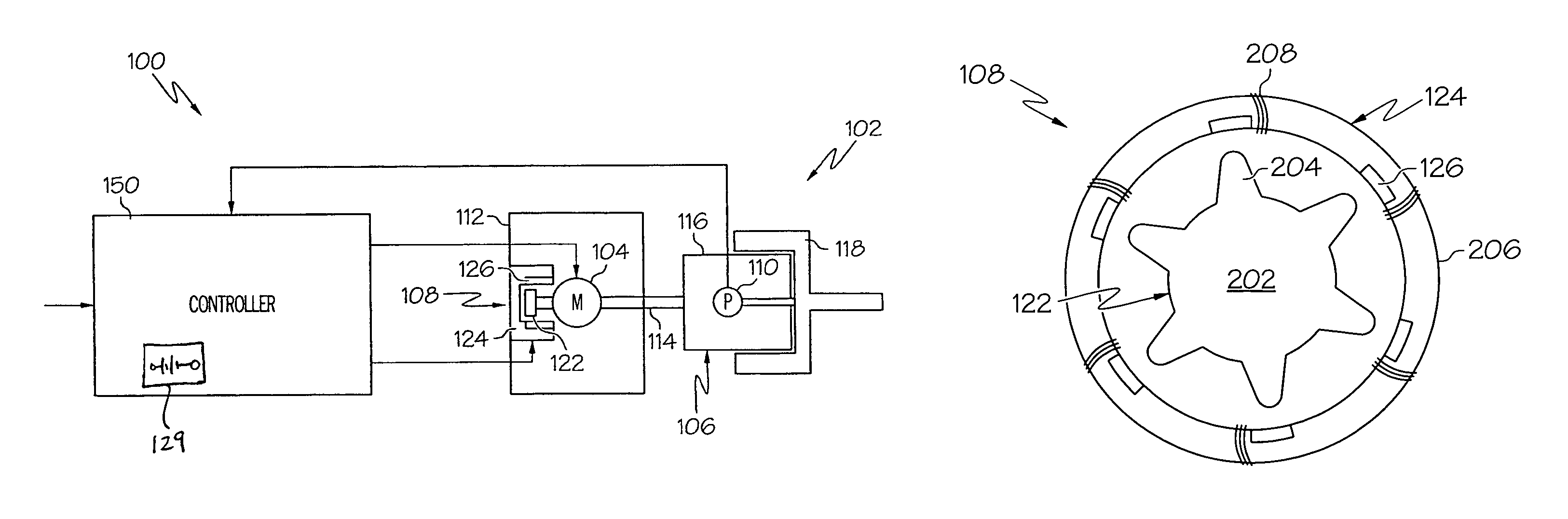
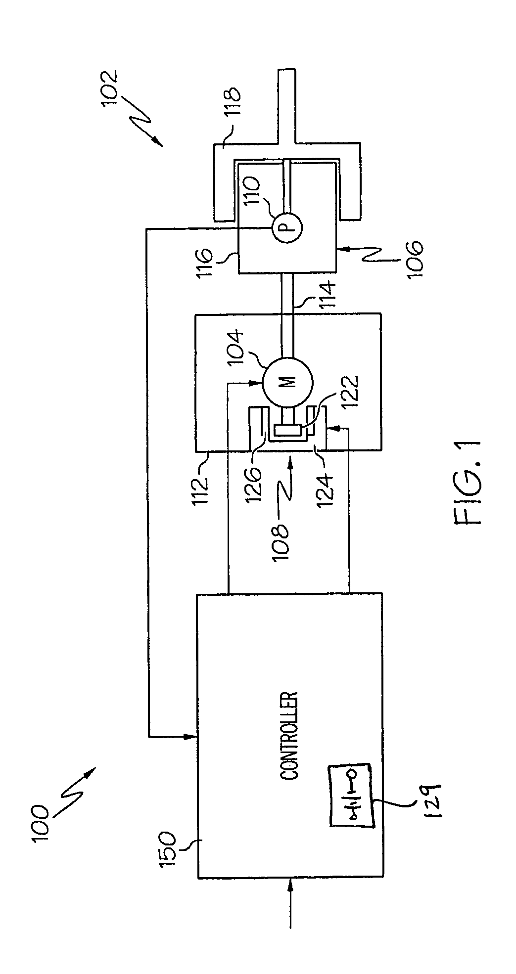
[0017]Turning now to FIG. 1, a functional block diagram of an exemplary actuator control system 100 is shown. The system 100, which may be used to control ...


PUM

PropertyMeasurementUnit
drive poweraaaaaaaaaa
permanent magnetic fieldaaaaaaaaaa
magnetic fieldaaaaaaaaaa

Abstract

A no-back device for a power drive unit is configured such that, during operation of the power drive unit, the no-back device does not supply magnetic or frictional force against power drive unit rotation. The no-back device is implemented either redundantly or no-redundantly, and includes a latch rotor and an electromagnet. In both embodiments, the latch rotor is coupled to the power drive unit to rotate therewith, and the electromagnet is coupled to receive a flow of current and, upon receipt thereof, generates a magnetic field force that opposes rotation of the latch rotor. In the redundant embodiment, the no-back device further includes one or more permanent magnets, and the magnetic field generated by the electromagnet selectively opposes or aids the magnetic field supplied by the permanent magnet(s).

Description

CROSS-REFERENCE TO RELATED APPLICATIONS[0001]This application claims the benefit of U.S. Provisional Application No. 60 / 736,819 filed Nov. 14, 2005, U.S. Provisional Application No. 60 / 736,977 filed Nov. 14, 2005, and U.S. Provisional Application No. 60 / 763,185 filed Jan. 26, 2006.TECHNICAL FIELD[0002]The present invention relates to actuators and, more particularly, to an electromagnetic latch for holding an actuator in position.BACKGROUND[0003]Actuators are used in myriad devices and systems. For example, many vehicles including, for example, aircraft, spacecraft, watercraft, and numerous other terrestrial and non-terrestrial vehicles, include one or more actuators to effect the movement of various control surfaces or components. In many applications such as, for example, aircraft flight surface control systems and aircraft thrust reverser actuation systems, the actuators include power drive units, such as motors, that are configured to receive a source of drive power to move an a...

Claims


Application Information

Patent Timeline
Patent Type & Authority Patents(United States)
IPC IPC(8): H01F7/14H02K7/10H02K49/00H02P15/00
CPCH02K7/106H02K49/106H02K7/06
Inventor POTTER, CALVIN C.HANLON, CASEYWINGETT, PAUL T.
Owner HONEYWELL INT INC
Why Eureka
Try Eureka