Color chart for adjusting colors and color adjusting method

a color chart and color adjustment technology, applied in the field of color chart for color adjustment, can solve the problems of distortion, distortion, and distortion of straight lines imaged as curves, and achieve the effect of erroneous judgments during color adjustmen

Inactive Publication Date: 2010-12-14
FUJIFILM CORP
View PDF4 Cites 56 Cited by
  • Summary
  • Abstract
  • Description
  • Claims
  • Application Information

AI Technical Summary

Benefits of technology

[0010]The present invention has been developed in view of the foregoing circumstances. It is an object of the present invention to provide a color chart that enables exact color adjustments without being influenced by distortion or peripheral light loss, and a color adjusting method.
[0024]The color chart of the present invention comprises the colored regions, which are separated by radially spreading line segments. Therefore, when imaging is performed with an imaging device that employs a wide angle lens, an image, on which influence due to distortion is minimal, can be obtained. In addition, by providing the achromatic colored regions at predetermined intervals, the influence due to peripheral light loss can be accurately detected. Accordingly, colors can be accurately adjusted.
[0025]If the achromatic colored regions are colored neutral gray, the influence of peripheral light loss is more easily observed than if the achromatic colored regions are white or black.

Problems solved by technology

However, it is not possible to uniformly illuminate the entirety of the interior of a body cavity with a point light source.
Therefore, distortion, in which straight lines are imaged as curves, occurs as well.
There is a possibility that the distortion and / or the peripheral light loss may cause erroneous judgments during color adjustment.
However, the influence caused by peripheral light loss and distortion cannot be completely eliminated, even if the aforementioned color chart comprising fan shaped colored regions is employed.
For this reason, the position within the color chart and changes in brightness cannot be accurately judged based on obtained images, and exact color matching cannot be performed.

Method used


Image

  • Color chart for adjusting colors and color adjusting method
  • Color chart for adjusting colors and color adjusting method
  • Color chart for adjusting colors and color adjusting method

Examples


Embodiment Construction

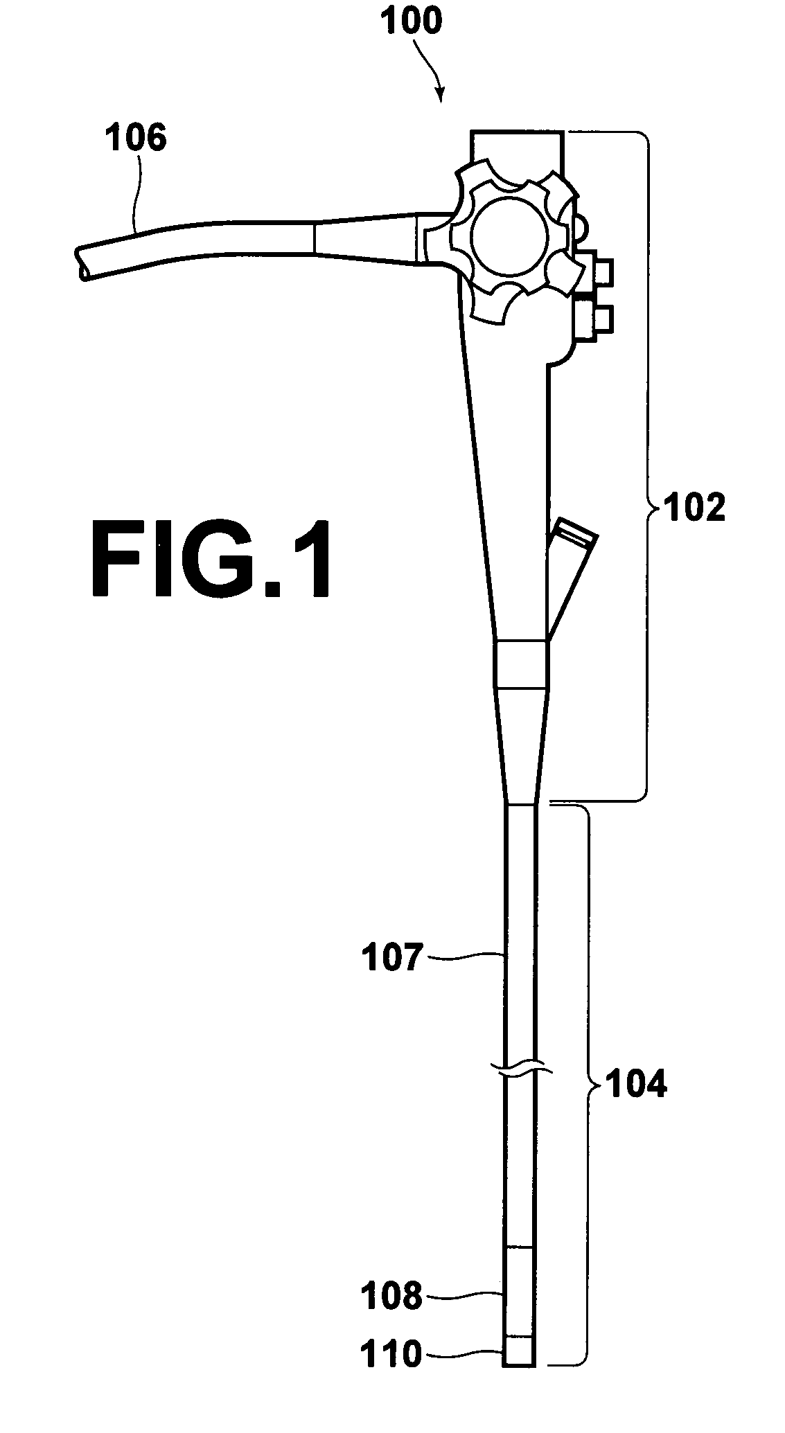
[0044]Hereinafter, an embodiment of the present invention will be described in detail with reference to the attached drawings. First, an endoscope 100 that performs imaging will be described with reference to FIG. 1 and FIG. 2.

[0045]As illustrated in FIG. 1, the endoscope 100 comprises: an operating portion 102; an insertion portion 104; and a connector portion (not shown) through which a universal cord 106 is drawn.

[0046]The connector portion is connected to a monitor for reproducing images, a light source apparatus, and the like.

[0047]The insertion portion 104, which is inserted into body cavities of patients, is continuous with the operating portion 102. The universal cord 106, which is connected to the light source apparatus and the like, is attached to the operating portion 102.

[0048]A large portion of the insertion portion 104 is a flexible portion 107, which bends in desired directions along an insertion path. An angling portion 108 is provided at the distal end of the flexib...


PUM


Abstract

A color chart that enables exact color adjustments without being influenced by distortion or peripheral light loss is provided. The color chart has a plurality of colored regions each being of a different color, separated by line segments that radiate outward from a predetermined point. A plurality of achromatic colored regions are provided among the plurality of colored regions at predetermined intervals.

Description

BACKGROUND OF THE INVENTION[0001]1. Field of the Invention[0002]The present invention relates to a color chart for color adjustment, and to a color adjusting method.[0003]2. Description of the Related Art[0004]Endoscopes are in wide use in the medical field. Point light sources of illuminating sections provided in the vicinities of imaging sections of color endoscopes illuminate the interiors of body cavities during imaging using endoscopes. Obtained images are reproduced by color monitors, color printers and the like.[0005]Observation and examination of the interiors of body cavities are based on images obtained by endoscopes. Therefore, it is desirable for the images to be output in colors as close to the actual colors as possible. However, different endoscopes have different color imaging ranges and color reproduction ranges. Accordingly, different color properties are exhibited by each endoscope.[0006]In addition, point light sources provided in the vicinities of imaging section...

Claims


Application Information

Patent Timeline
Patent Type & Authority Patents(United States)
IPC IPC(8): H04N1/40
CPCH04N1/60A61B1/00057
Inventor DONOMAE, YOSHIFUMI
Owner FUJIFILM CORP
Why Eureka
Try Eureka