Wireless communication apparatus and method

a communication apparatus and wireless technology, applied in the field of wireless communication schemes, can solve the problems of great reduction in throughput, and achieve the effects of reducing the success probability of blockack frame and blockackrequest frame, excessive deterioration in communication efficiency, and reducing throughpu

Active Publication Date: 2010-12-14
PALMIRA WIRELESS AG
View PDF14 Cites 10 Cited by
  • Summary
  • Abstract
  • Description
  • Claims
  • Application Information

AI Technical Summary

Benefits of technology

[0016]In contrast, as the transmission rate is increased to realize high-speed transmission / reception of data frames, the transmission success probability of BlockAck frames and BlockAckRequest frames decrease. As a consequence, an initiator or responder which has failed in receiving a BlockAck frame or a BlockAckRequest frame needs to retransmit it. This leads to excessive deterioration in communication efficiency, i.e., a great reduction in throughput. The present invention has been made to solve the above problem, and has as its object to increase the transmission success probability of frames used for acknowledgement, e.g., a BlockAck frame or a BlockAckRequest frame.

Problems solved by technology

This leads to excessive deterioration in communication efficiency, i.e., a great reduction in throughput.

Method used


Image

  • Wireless communication apparatus and method
  • Wireless communication apparatus and method
  • Wireless communication apparatus and method

Examples


first embodiment

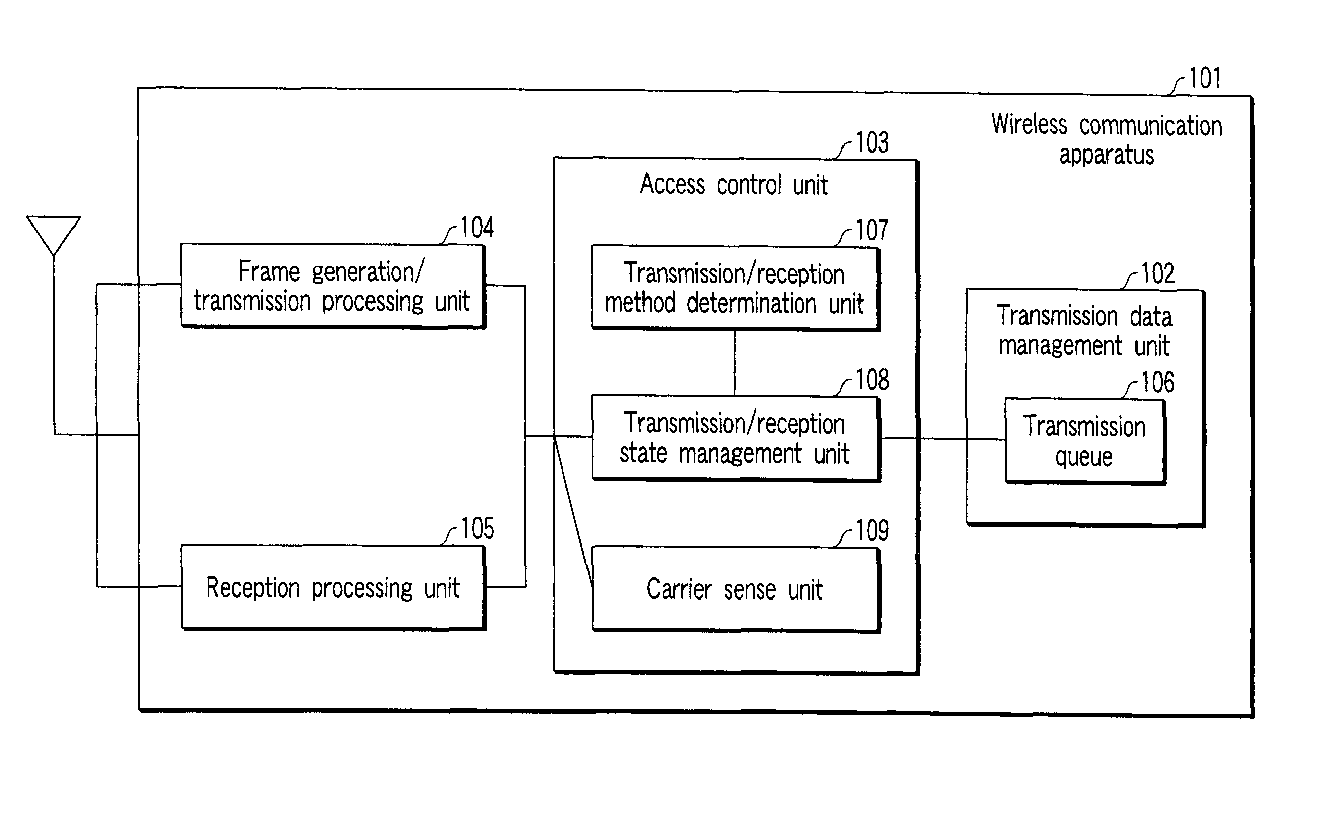
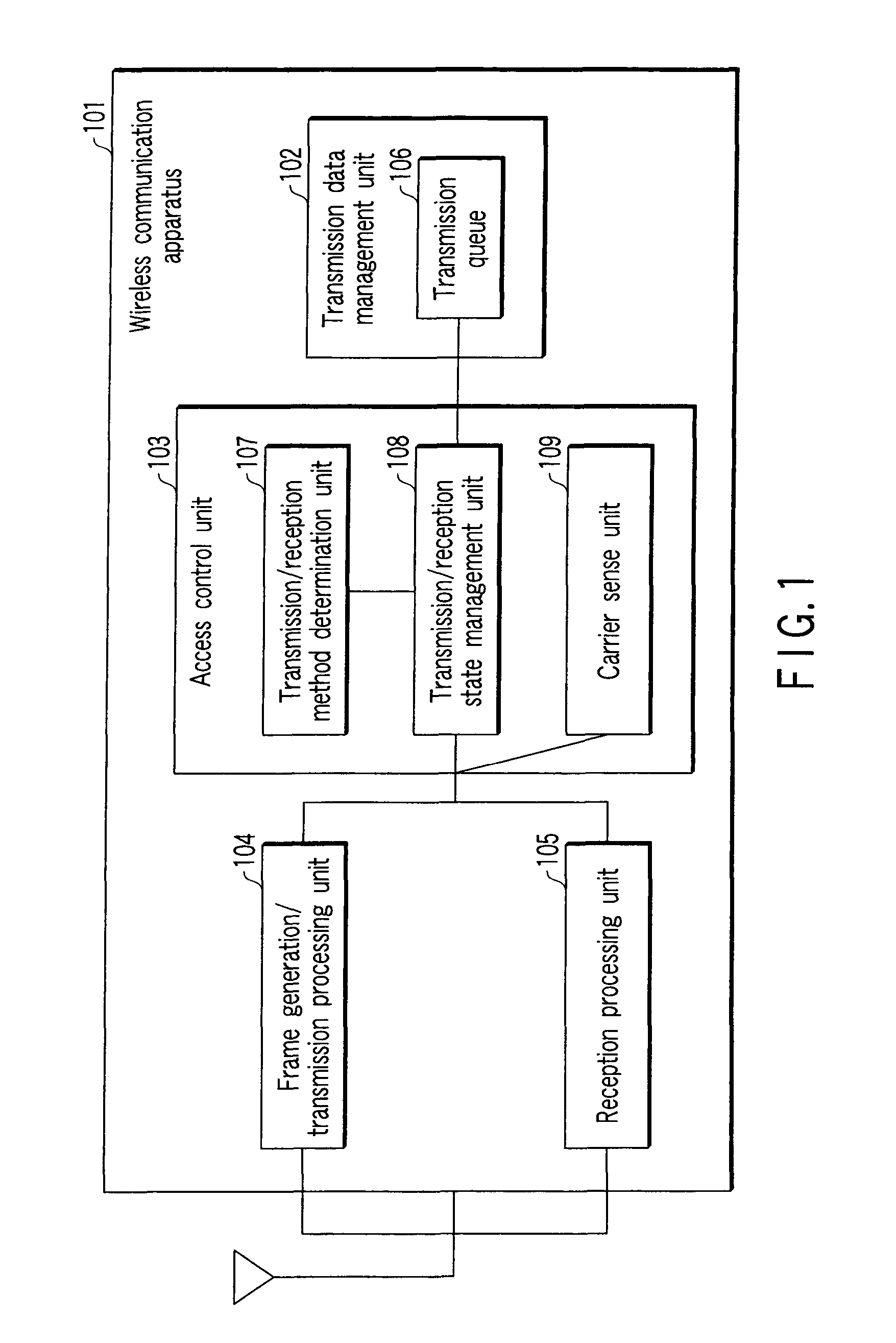
[0043]FIG. 1 is a block diagram associated with an example of a wireless communication apparatus 101 which supports the contents proposed in IEEE 802.11n wireless LAN communication specifications. That is, the following description will be made on the assumption that a high transmission rate in the Multiple Input, Multiple Output (MIMO) scheme proposed in IEEE 802.11n and the transmission scheme in which the frequency band is extended from the 20 MHz band to the 40 MHz band are supported.

[0044]Assume that the contents proposed in IEEE 802.11n described below include all the IEEE 802.11 standard specifications, IEEE 802.11a / b / g / e, and the like (including those regarded as amendments, recommended practices, and the like).

[0045]It is needless to say that IEEE 802.11n is an example, and the present invention can be applied to wireless communication schemes, in general.

[0046]The wireless communication apparatus 101 comprises a transmission data management unit 102, access control unit 10...

first modification

of First Embodiment

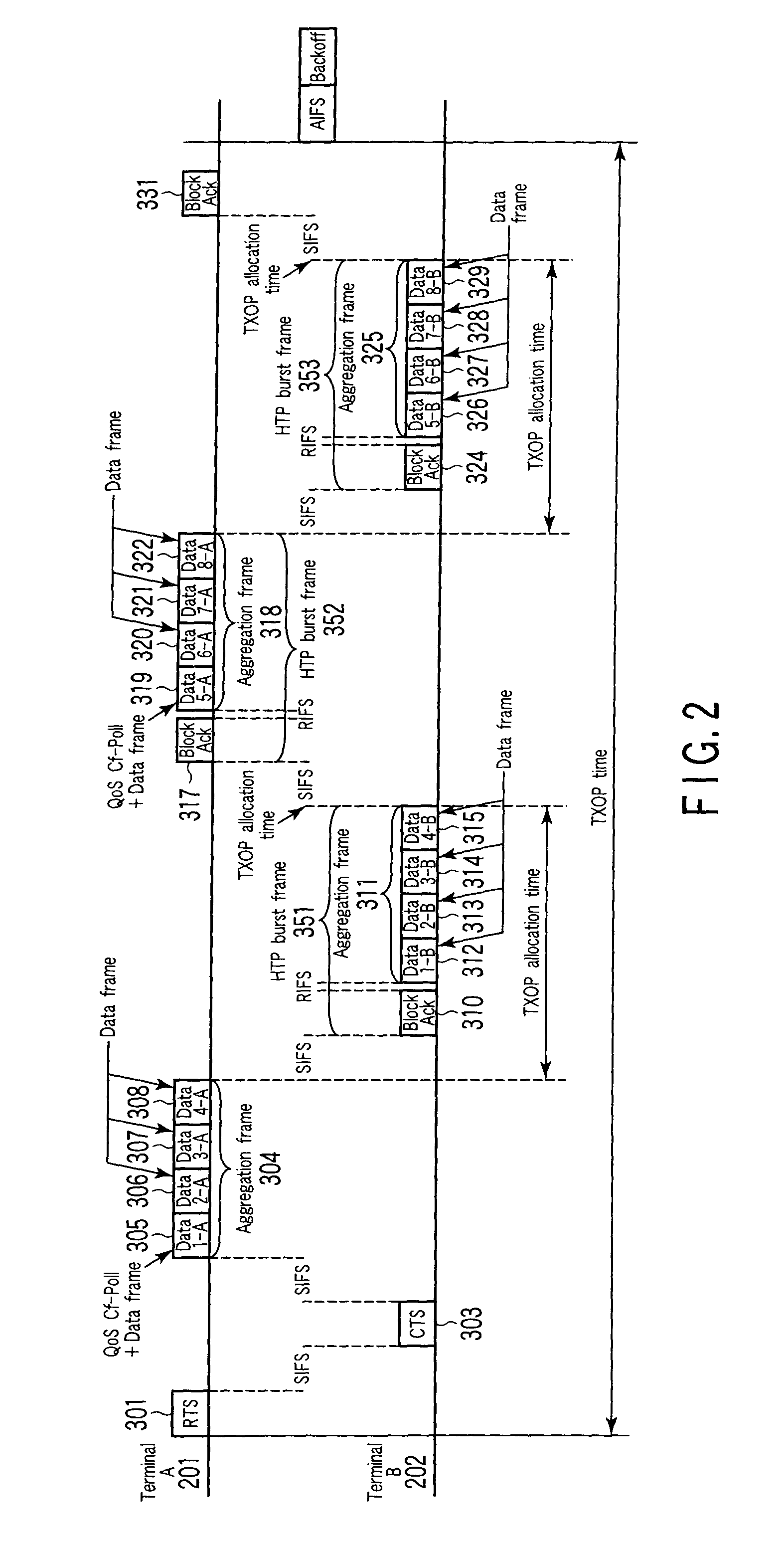
[0135]In the first embodiment, the terminal A 201 writes the TXOP allocation time in a QoS Cf-Poll+Data frame. That is, the terminal A 201 notifies the terminal B 202 of the TXOP allocation time. The terminal B 202 transmits transmission data of an amount which does not exceed an amount corresponding to the allocated TXOP allocation time.

[0136]However, the terminal B 202 may be designed to transmit transmission data as much as it wants to transmit regardless of the TXOP allocation time.

[0137]In such a case, the terminal A 201 need not write the TXOP allocation time in a QoS Cf-Poll+Data frame. It suffices to arbitrarily set the amount of transmission data which the transmission / reception state management unit 108 extracts from the transmission queue 106 and transfers to the frame generation / transmission processing unit 104 in step 105 or 112 in FIG. 4.

[0138]Even in this arrangement, the terminal A 201 can receive transmission data without any problem because only ...

second modification

of First Embodiment

[0139]FIG. 6 is a block diagram showing an example of a wireless communication apparatus 1101 according to the second modification. FIG. 7 is a flowchart associated with the operation of a terminal A 201. FIG. 8 is a flowchart associated with the operation of a terminal B 202.

[0140]The first embodiment has exemplified the case wherein the terminal A 201 and the terminal B 202 each use, as the value of NAV to be written in a frame which the terminal is to transmit, the value obtained by subtracting the time taken for the transmission of a frame from the self terminal, the SIFS time, and the time taken for the next transmission of a BlockAck frame from the remote terminal from the value of NAV written in a control frame or data frame received from the remote terminal.

[0141]This modification will exemplify an arrangement in which the value obtained by subtracting the time taken for the transmission of a frame from the self terminal, the SIFS time, and the time taken ...


PUM


Abstract

A wireless communication apparatus performs bi-directional communication with an initiator. The apparatus is allocated an allocation period for data transmission from the initiator. The apparatus includes means for generating a first physical frame including an acknowledgement frame with respect to data received from the initiator, and generating a second physical frame in which a plurality of transmission data frames addressed to the initiator are aggregated. The apparatus also includes means for transmitting the first physical frame at a first transmission rate and the second physical frame at a second transmission rate, during the allocation period.

Description

CROSS-REFERENCE TO RELATED APPLICATIONS[0001]This is a Continuation Application of PCT Application No. PCT / JP2006 / 306985, filed Mar. 27, 2006, which was published under PCT Article 21(2) in English.[0002]This application is based upon and claims the benefit of priority from prior Japanese Patent Application No. 2005-178584, filed Jun. 17, 2005, the entire contents of which are incorporated herein by reference.BACKGROUND OF THE INVENTION[0003]1. Field of the Invention[0004]The present invention relates to implementing a wireless communication scheme which is robust even in a poor wireless propagation environment in a wireless communication system including wireless communication devices such as cellular phones and wireless LANs which perform transmission / reception of data through wireless medium.[0005]2. Description of the Related Art[0006]According to wireless LAN specification IEEE 802.11e which has realized enhancement associated with the Quality of Service (QoS) of a Medium Acces...

Claims


Application Information

Patent Timeline
Patent Type & Authority Patents(United States)
IPC IPC(8): H04B1/44H04J3/16H04L12/28H04W28/04H04W28/22H04W72/04H04W84/12
CPCH04L1/1614H04W74/0816H04W84/12H04W28/22H04L1/1678H04L1/1854
Inventor NAKAJIMA, TETSUADACHI, TOMOKOTAKAGI, MASAHIROTANDAI, TOMOYAUTSUNOMIYA, YORIKONABETANI, TOSHIHISA
Owner PALMIRA WIRELESS AG
Why Eureka
Try Eureka