Loader boom control system

a control system and loader technology, applied in agricultural machines, applications, instruments, etc., can solve the problems of affecting the performance of the loader, the bucket on the boom being stuck or stalled, and the operator being more adept, so as to reduce the engine speed, reduce the tractive effort, and eliminate the velocity error

Active Publication Date: 2010-12-14
DEERE & CO
View PDF31 Cites 35 Cited by
  • Summary
  • Abstract
  • Description
  • Claims
  • Application Information

AI Technical Summary

Benefits of technology

[0007]The controller may use a predefined algorithm to de-rate the tractive effort of the wheels. The controller may also control the boom actuator to adjust the boom velocity to eliminate the velocity error. The tractive effort of the wheels can be de-rated as a function of the power train configuration, which may include a torque converter, and the tractive effort may be reduced by reducing the engine speed.

Problems solved by technology

One problem with loaders, though, is that some operators tend to be more adept at maneuvering the boom into and picking up a load of material.
If an operator is not skilled in maneuvering the boom to the pile, it may directly affect the loader's performance.
The operator may cause the bucket on the boom to become stuck or stalled in the material, requiring additional time and manipulation to free it.

Method used


Image

  • Loader boom control system
  • Loader boom control system
  • Loader boom control system

Examples


Embodiment Construction

[0020]For the purposes of promoting an understanding of the principles of the invention, reference will now be made to the embodiments illustrated in the drawings, which are described below. It will nevertheless be understood that no limitation of the scope of the invention is thereby intended. The invention includes any alterations and further modifications in the illustrated devices and described methods and further applications of the principles of the invention, which would normally occur to one skilled in the art to which the invention relates.

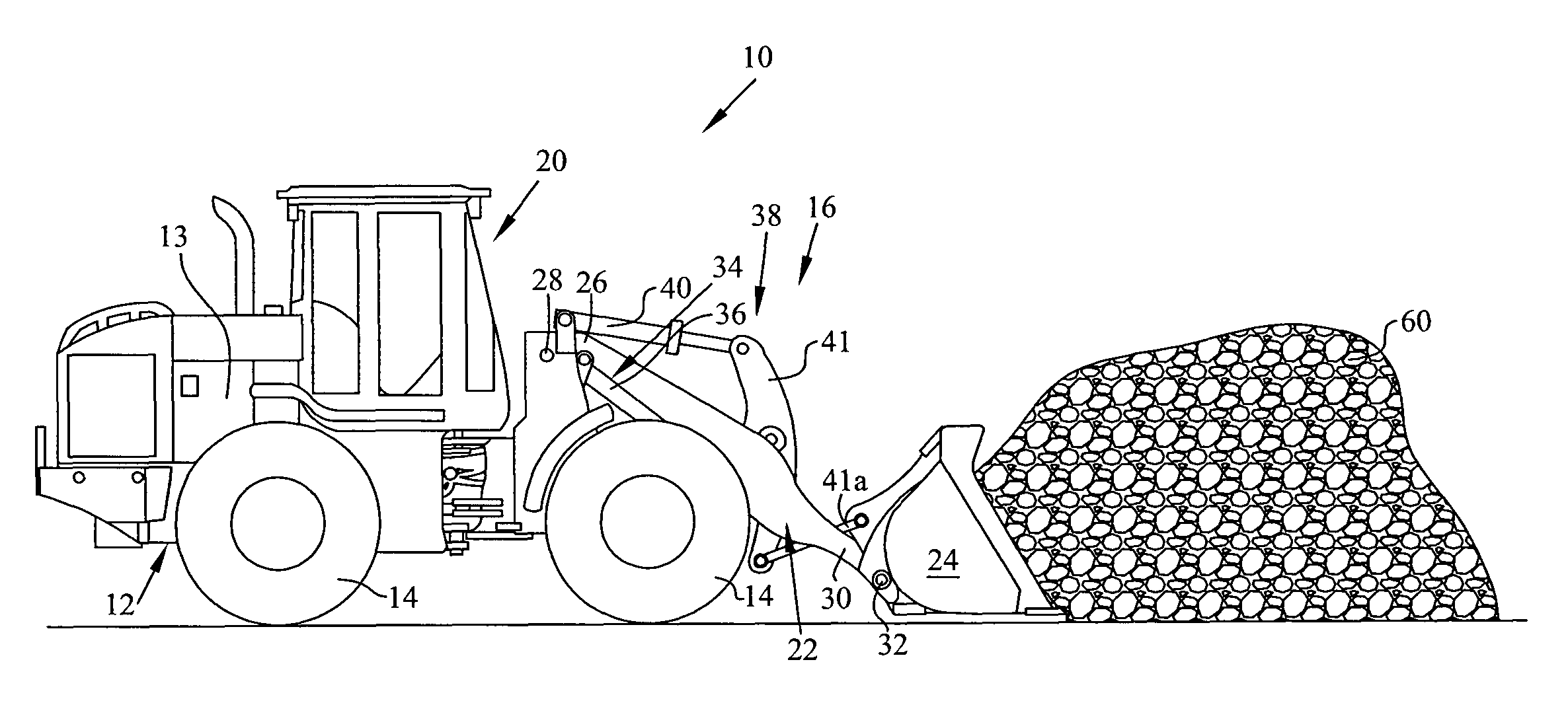
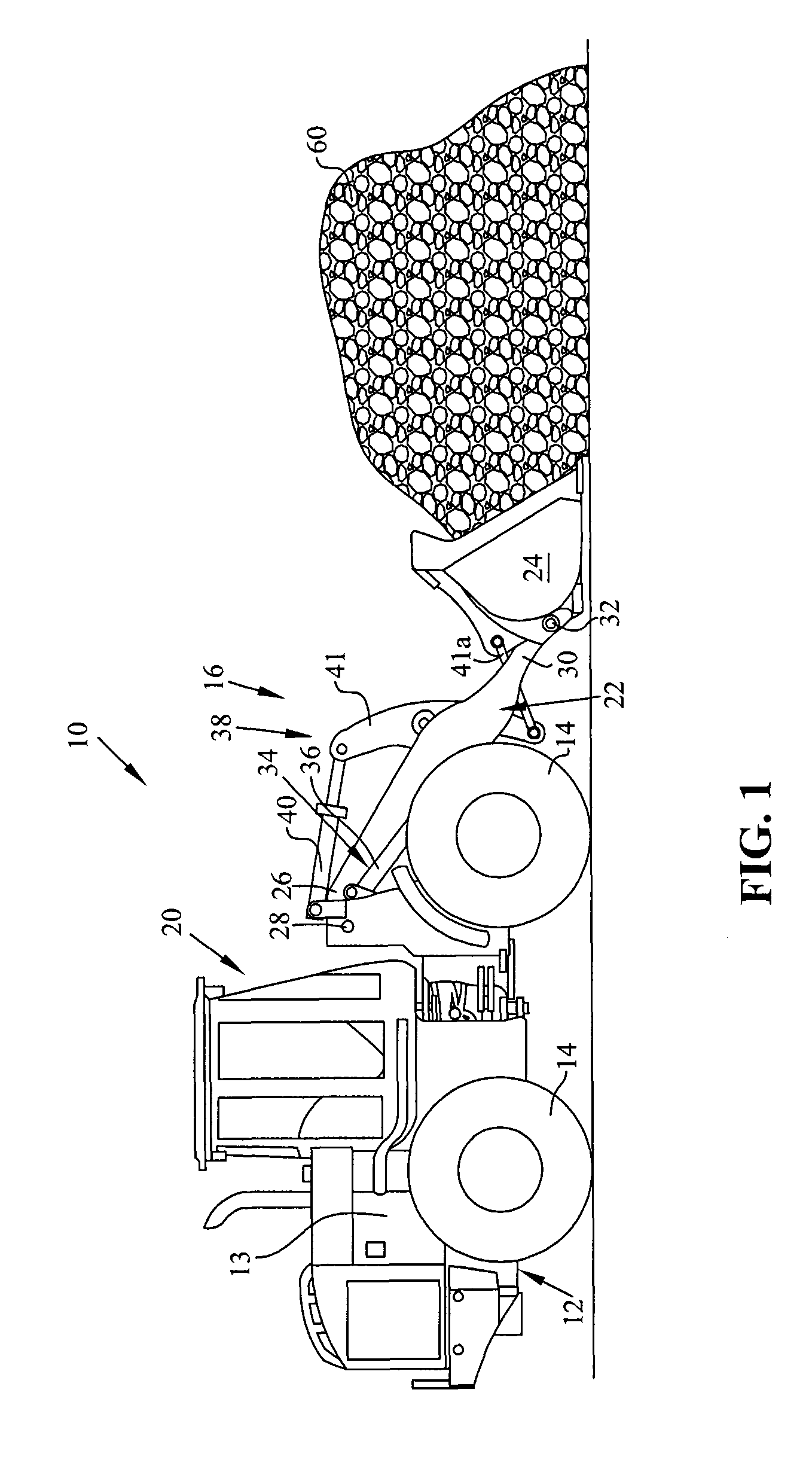
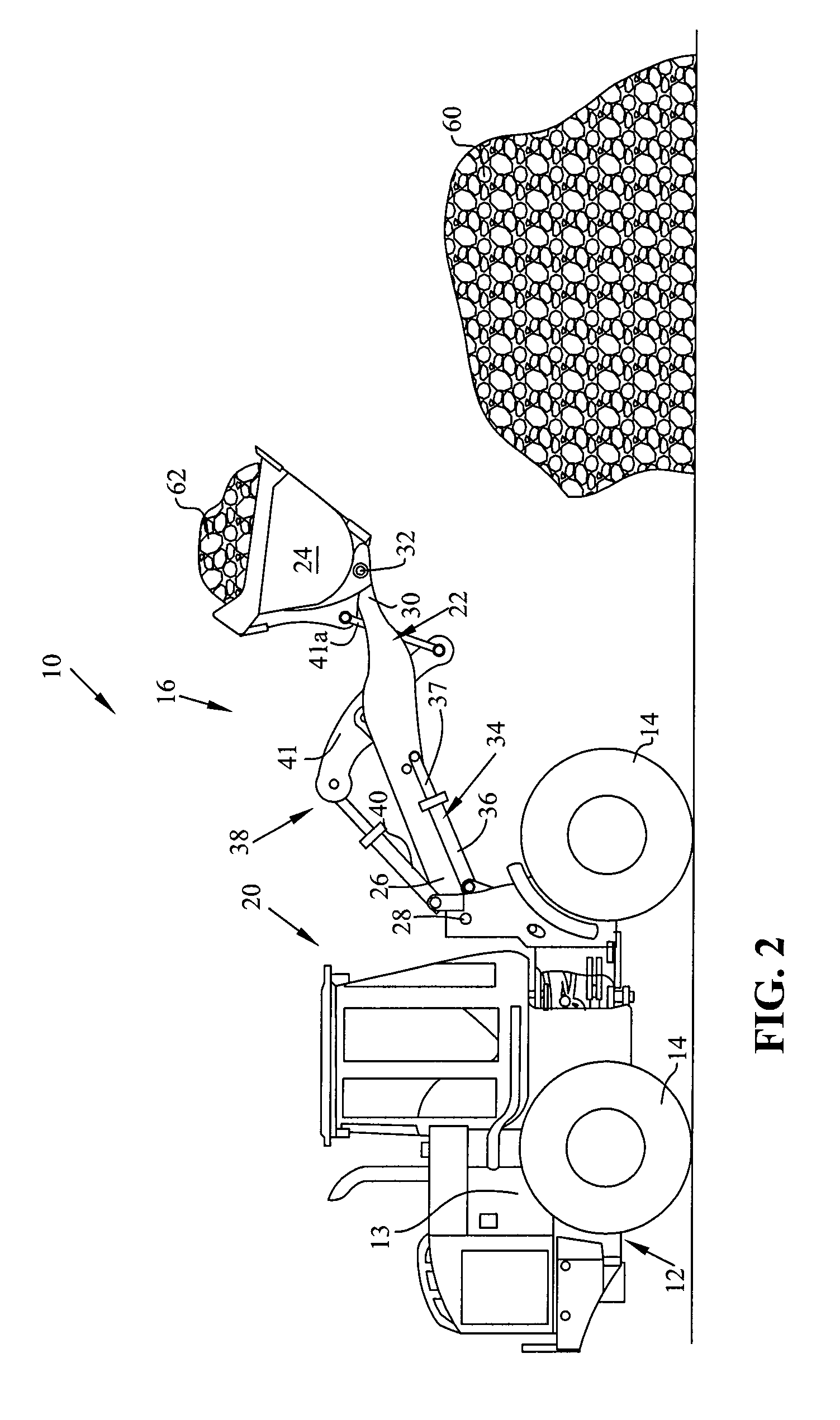
[0021]Now referring to FIGS. 1 and 2, in one embodiment of the invention a self-propelled work vehicle is provided, such as a loader, and generally indicated as 10. Loader 10 includes a frame, generally indicated as 12, an engine 13, ground engaging wheels 14, which are attached to frame 12 in a manner that allows rotational movement relative thereto, as is known, and a loader assembly, generally indicated as 16. The loader assembly can p...


PUM


Abstract

A work vehicle that includes a boom; a boom actuator connected to the boom, the boom actuator being adapted to controllably move the boom about a boom pivot in response to receiving a boom control signal; and a controller having computational and time-keeping capabilities. The controller communicates with the boom actuator, and calculates the boom velocity, compares the calculated velocity to a commanded velocity to obtain a velocity error, and, if necessary, de-rates the tractive effort of the wheels to prevent the boom from stalling. The controller also determines if the operator is actuating the boom, and reads the boom position to calculate the boom velocity based upon the current boom position and a previous boom position. The controller uses a predefined algorithm to de-rate the tractive effort of the wheels as a function of the power train configuration.

Description

BACKGROUND OF THE INVENTION[0001]The present invention relates generally to a control for a loader boom, and in particular, to a loader boom control designed to maintain consistent boom performance regardless of the operator to avoid boom stall problems.[0002]Numerous types of machines are available that can be equipped with one or more tools to perform a work function. One type of such a work machine is commonly called a wheel loader and may be used to load material from a pile. One problem with loaders, though, is that some operators tend to be more adept at maneuvering the boom into and picking up a load of material. A skilled operator uses an appropriate boom velocity and traction force / rimpull to enable the bucket to smoothly pick up as much material as possible. If an operator is not skilled in maneuvering the boom to the pile, it may directly affect the loader's performance. The operator may cause the bucket on the boom to become stuck or stalled in the material, requiring ad...

Claims


Application Information

Patent Timeline
Patent Type & Authority Patents(United States)
IPC IPC(8): G06F19/00G08B21/00
CPCE02F9/2029E02F9/2253
Inventor ANDERSON, ERIC R
Owner DEERE & CO
Why Eureka
Try Eureka