Conduit trap and condensation recovery device

a trap and condensation technology, applied in the direction of bends, separation processes, domestic cooling apparatus, etc., can solve the problems of inconvenient if not impossible refilling of traps, inconvenient and difficult refilling of traps, and inability to easily access refrigeration drains

Active Publication Date: 2010-12-21
ZATARAIN JESUS M
View PDF11 Cites 20 Cited by
  • Summary
  • Abstract
  • Description
  • Claims
  • Application Information

AI Technical Summary

Benefits of technology

[0008]The present invention provides a conduit gas trap for use in refrigeration system drain lines to prevent sewer gas back-up during periods of dry weather or under-use where a standard P or S trap would fail due to evaporation.
[0018]To facilitate cleaning of the conduit trap and condensation recovery a clean-out port can be included in, for example at the top of the upper conduit, and can be fitted with a removable cap can to prevent dirt and foreign objects from becoming lodged in the conduit trap. Either the cap of the clean out port can be threaded, with the other part adapted to receive such threads. Alternatively, the removable can cover the clean-out port by means of a compression fitting or a hinged fitting.

Problems solved by technology

However, in periods of infrequent use, the fluid may evaporate from such traps, allowing gas to enter an occupied space.
Unlike residential plumbing drains, however, refrigeration drains may not be easily accessible for manual refilling.
Furthermore, a water source, such as a water supply line, is not usually installed in connection with a refrigeration drain trap, making refilling of the trap inconvenient if not impossible.
The availability of sources of pure, fresh water are dwindling in many areas of the world as populations expand in areas where fresh water supplies are limited.

Method used


Image

  • Conduit trap and condensation recovery device
  • Conduit trap and condensation recovery device
  • Conduit trap and condensation recovery device

Examples


Embodiment Construction

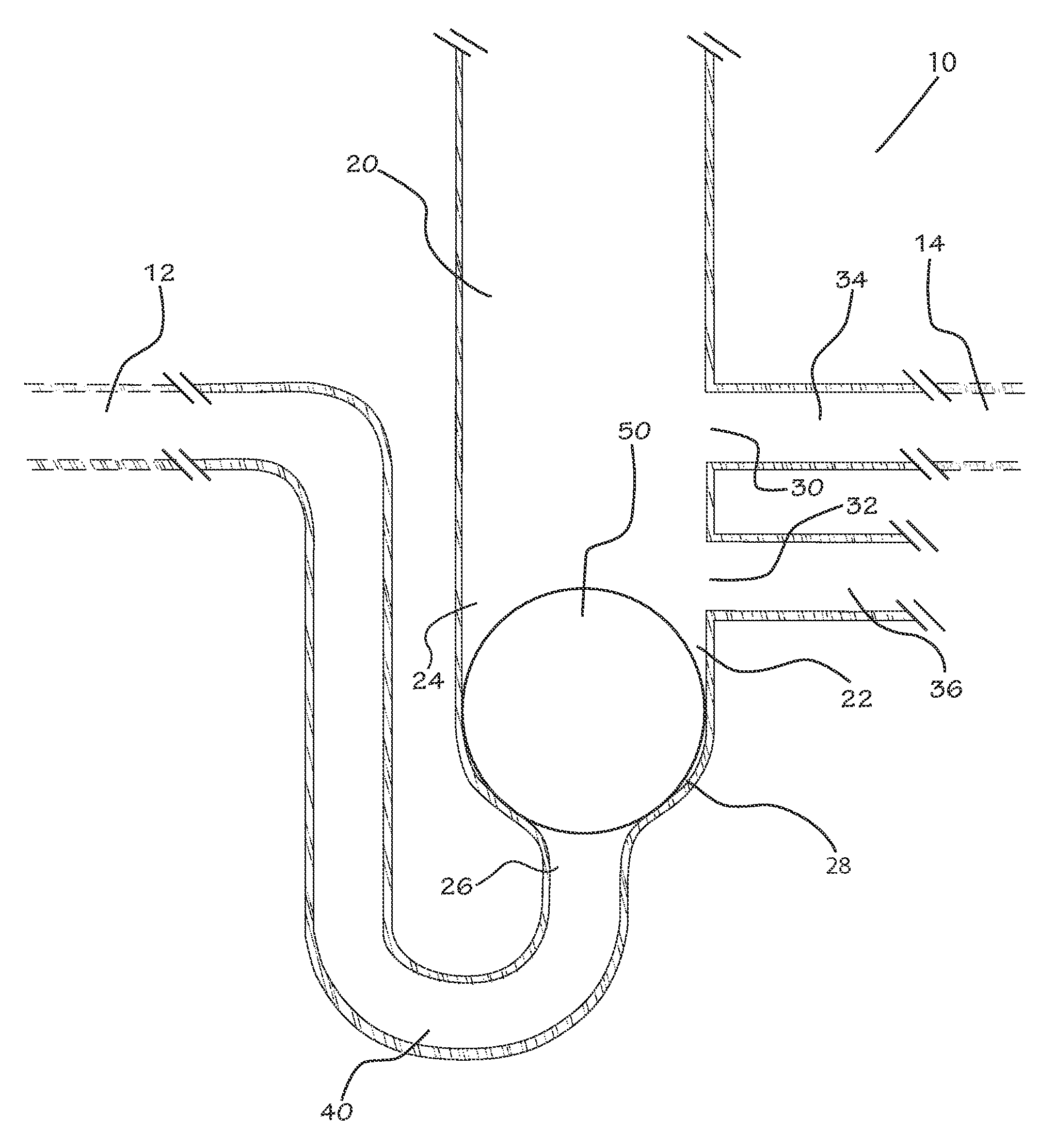
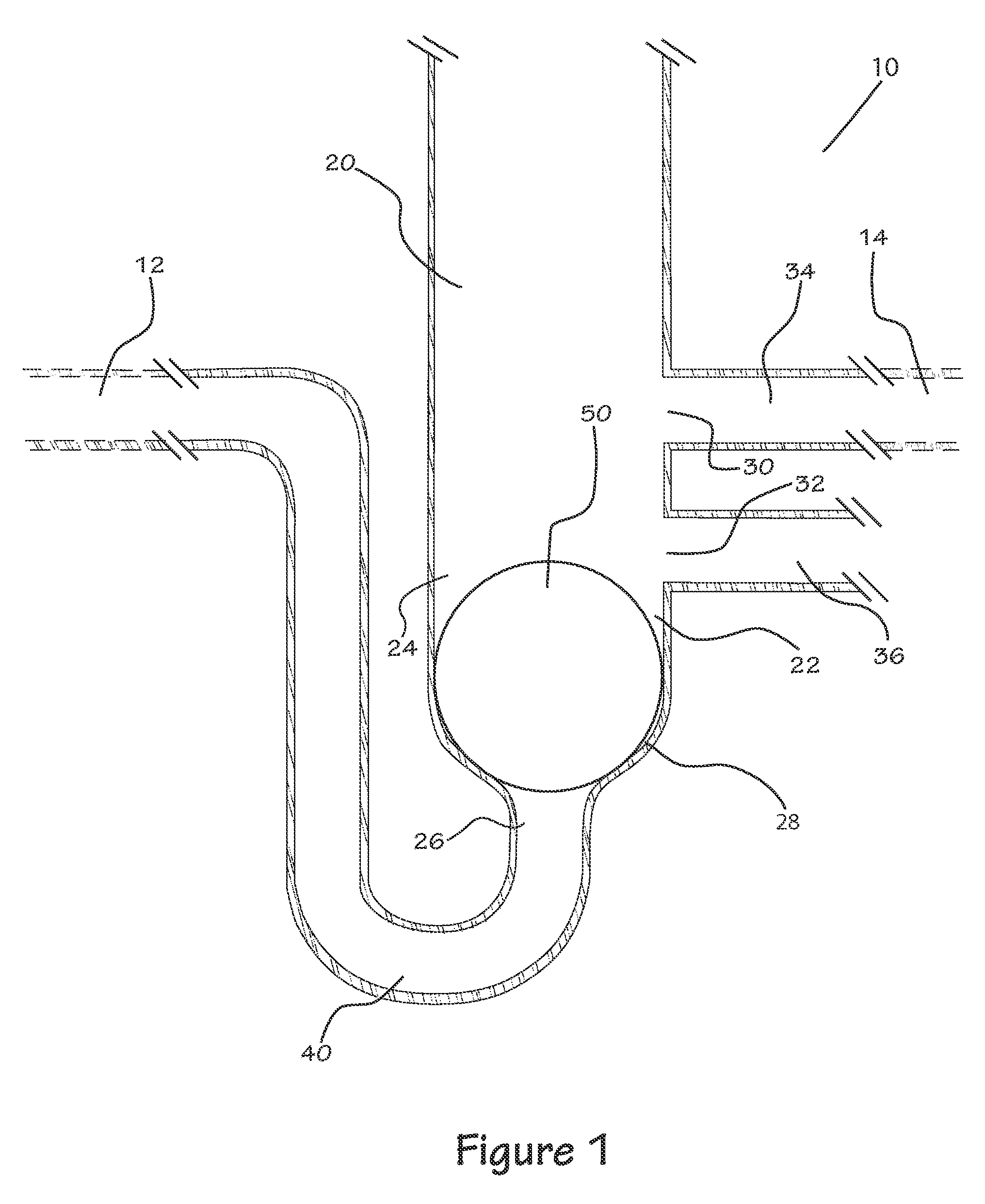
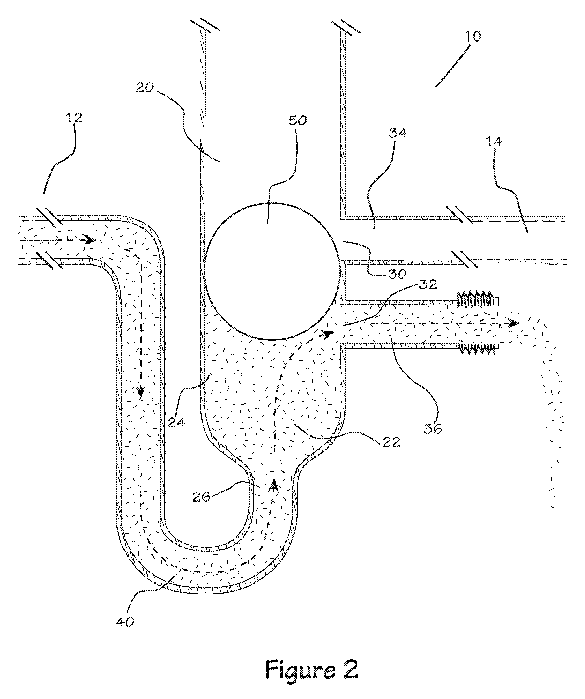
[0028]Referring to the drawings and in particular to FIG. 1, the conduit trap of the present invention is shown generally at 10 as installed in a refrigeration system drainage line 12, and connected to a sewer line 14. As used herein, “conduit” refers to a channel, such as a pipe or tube through which fluid is conveyed. The conduit trap 10 can be generally understood as a hollow body defining a directional fluid path from refrigeration system drainage line 12 to sewer line 14. The hollow body includes an upper conduit 20, which is installed in a substantially vertical position. Disposed on upper conduit is at least one fluid outlet, such as waste outlet 30, condensation collection outlet 32, or both a waste outlet 30 and a condensation collection outlet 32 as illustrated in FIG. 1. As described below in greater detail, when both waste outlet 30 and condensation collection outlet 32 are present, waste outlet 30 is preferably disposed above condensation collection outlet 32. In order ...


PUM

PropertyMeasurementUnit
diameteraaaaaaaaaa
outer circumferenceaaaaaaaaaa
inner circumferenceaaaaaaaaaa

Abstract

The present invention provides a conduit trap, which can also operate as condensation recovery device when installed in a refrigeration system drainage line. The conduit trap is generally a hollow body defining a fluid path that includes an upper conduit 20, having a waste outlet 30 and optionally a condensation collection outlet 32. A lower conduit 22 extends downwardly from the upper conduit and has a narrowing that creates an inner sealing region for receiving a sealing means, such as float 50. Condensation can be directed from the refrigeration system through the conduit trap for recovery or for disposal without exposing the refrigeration drainage line and occupied space in which the refrigeration unit is located to sewer gasses even in dry weather when a gravity based, fluid-filled trap would fail.

Description

FIELD OF THE INVENTION[0001]The present invention relates generally to the field of refrigeration drainage. More particularly, it relates to a conduit trap that can be used to prevent sewer gas back up in a drainage line from a refrigeration system. The present invention is useful under dry conditions, when the refrigeration system is turned off and when used intermittently. The conduit trap of the invention can also be adapted for recovering water from refrigeration condensation. The invention also relates methods for recovering water from refrigeration condensation using a conduit trap of the invention.BACKGROUND[0002]Refrigeration systems are used in air conditioners, dehumidifiers, refrigerators, freezers and the like, including commercial coolers, meat lockers, cold rooms, walk-in freezers and walk-in refrigerators. Typical refrigeration systems pass air over fluid- or gas-filled coils, typically with the aid of a fan. A desired refrigeration temperature is achieved through the...

Claims


Application Information

Patent Timeline
Patent Type & Authority Patents(United States)
IPC IPC(8): F24F13/22F25D21/14F16K13/10
CPCF25D21/14Y10T137/4463Y10T137/4471Y10T137/4478Y10T137/4501
Inventor ZATARAIN, JESUS M.
Owner ZATARAIN JESUS M
Why Eureka
Try Eureka