Spark ignition engine

Inactive Publication Date: 2010-12-28
YANMAR POWER TECHNOLOGY CO LTD
View PDF20 Cites 27 Cited by
  • Summary
  • Abstract
  • Description
  • Claims
  • Application Information

AI Technical Summary

Benefits of technology

[0015]The effects of the present invention are described below.
[0016]According to the present invention, the standard ignition plugs can be used for the spark ignition engine and cost reduction can be achieved. The flame jet can be generated by the flame blown into the combustion chamber out of the auxiliary chamber through the nozzle holes provided in the sleeve, so that the flame jet can generate the turbulence, which makes rapid combustion possible without the conventional auxiliary chamber type ignition plug. Moreover, the nozzle holes can be provided away from the explosion surface of the piston, so that the flame jet can be prevented from being affected by the temperature of the explosion surface. Furthermore, the auxiliary chamber can be simply formed, so that the auxiliary chamber can be freely designed, the position of ignition can be freely disposed and, thus, the auxiliary chamber that is capable of preventing from being affected by the residual gas can be easily formed.
[00

Problems solved by technology

Thus, the diameter of the auxiliary chamber is limited by the diameter of the ignition plug.
As a result, the ignition in the auxiliary chamber or the flame expan

Method used


Image

  • Spark ignition engine
  • Spark ignition engine
  • Spark ignition engine

Examples


Embodiment Construction

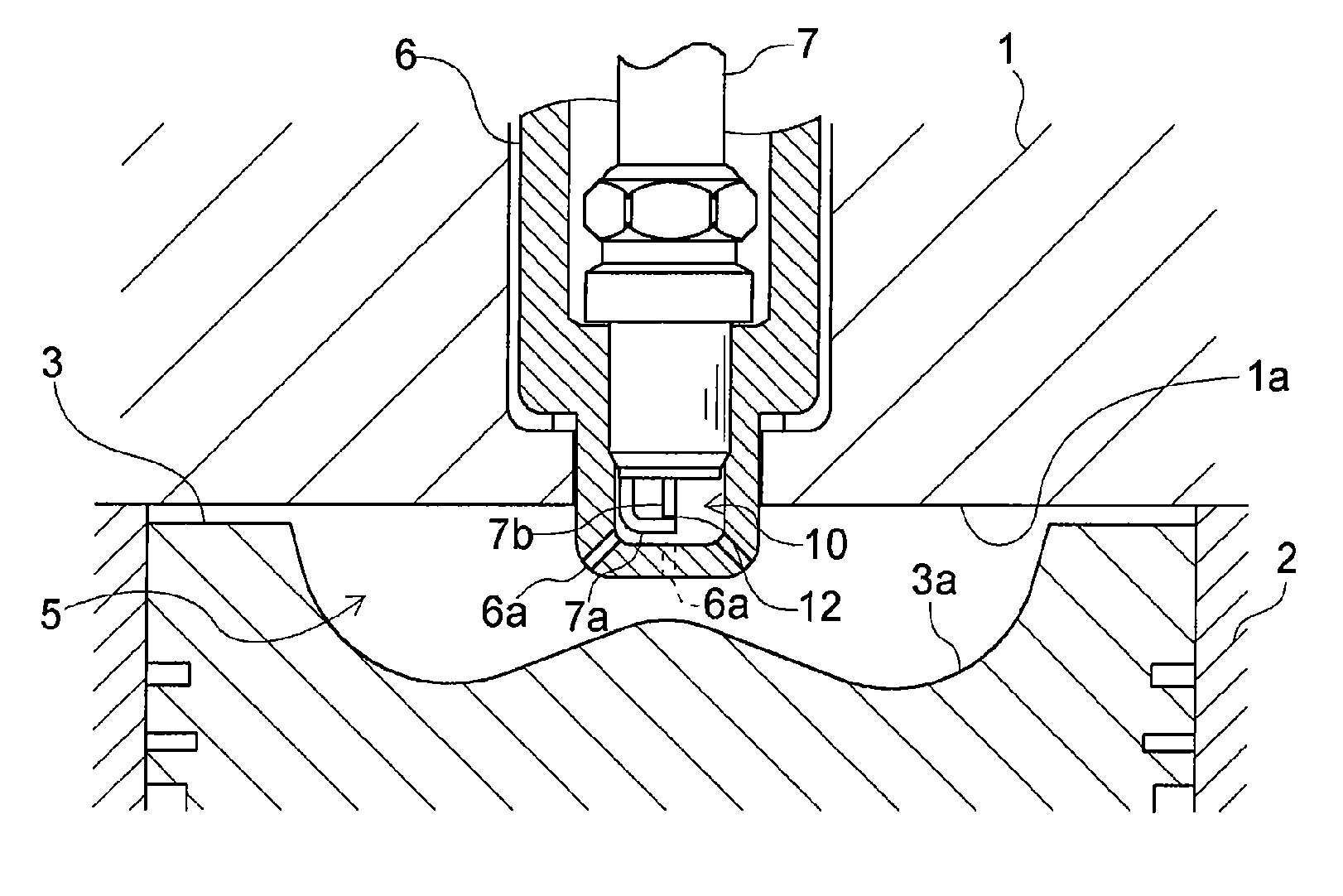
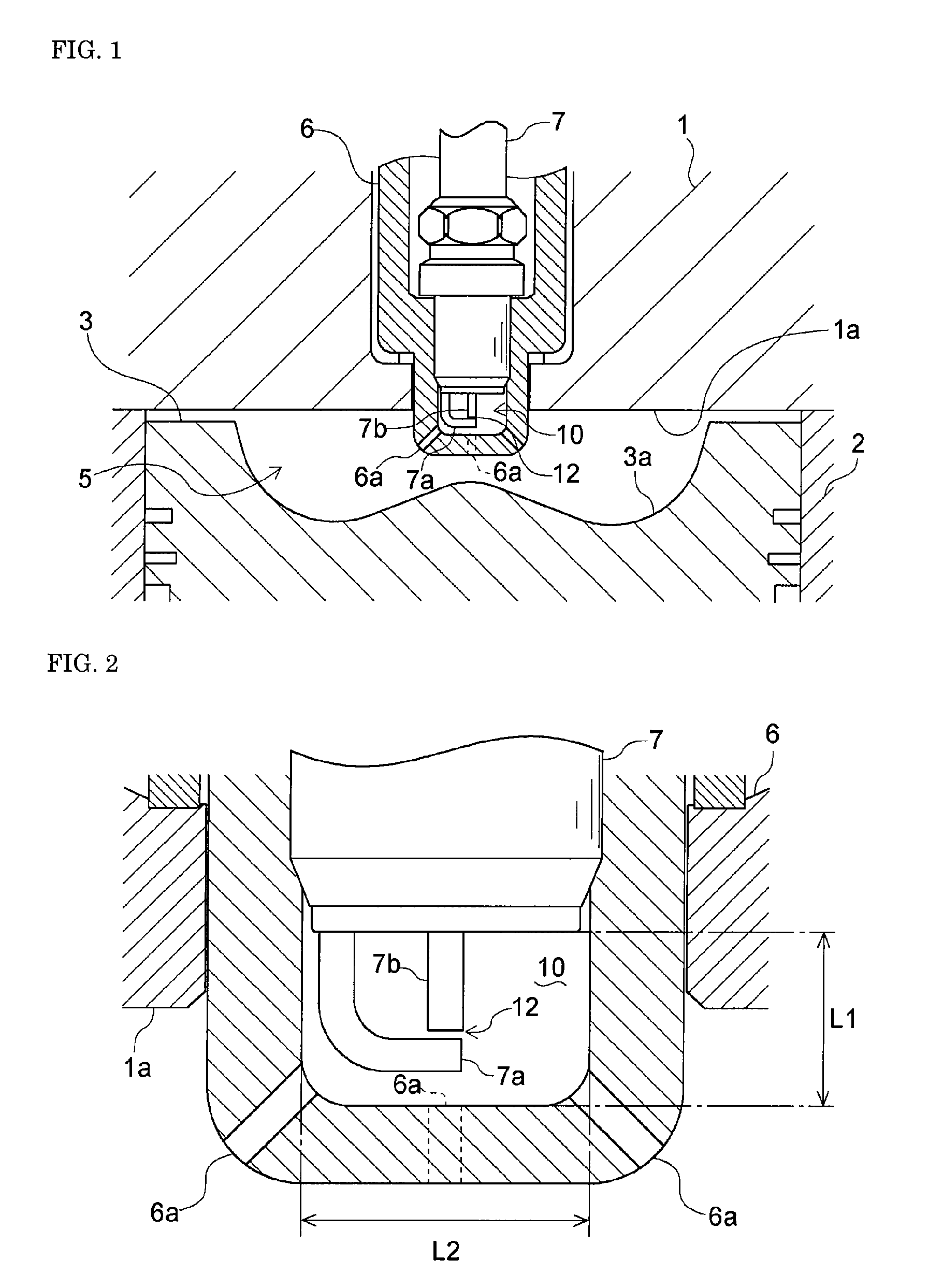
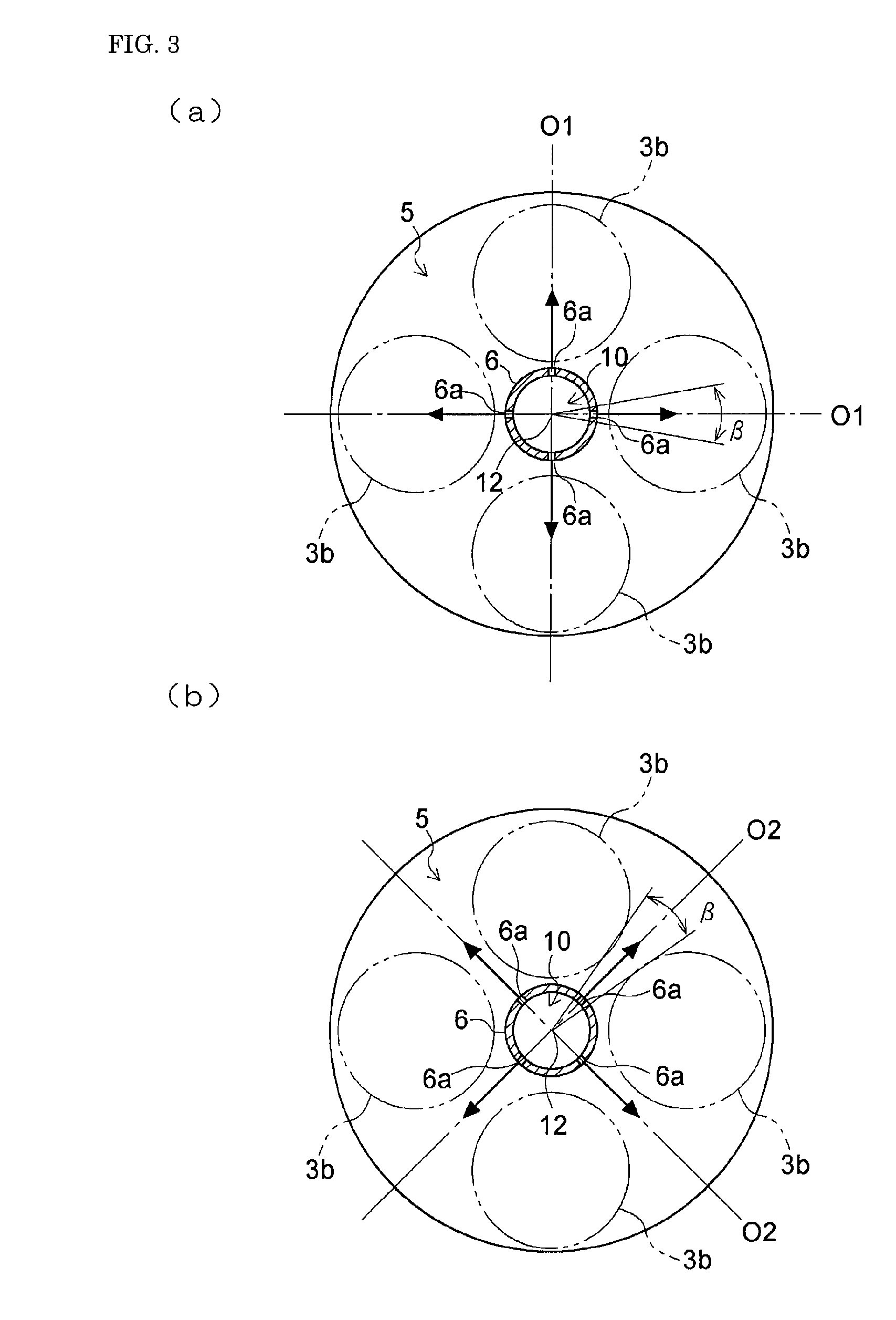
[0041]In the spark ignition engine according to the present invention, as shown in FIGS. 1 and 2, a cylinder 2 is disposed under a cylinder head 1 and a piston 3 is slidably installed in the cylinder 2 in the vertical direction. A concave-shaped surface 3a is formed at the upper end of the piston 3, facing the cylinder head 1. A combustion chamber 5 is formed as the space surrounded by the cylinder head 1, the cylinder 2 and the concave-shaped surface 3a. An intake valve and an exhaust valve (both not shown) are provided in the cylinder head 1, facing respective valve recesses 3b provided on the piston 3 (see FIG. 3). By opening and shutting the intake valve and the exhaust valve alternately, the intake and exhaust for the combustion chamber 5 can be carried out.

[0042]A sleeve 6, which is formed in the blind cylindrical shape, is fitted in the vertical direction at the center of the cylinder head 1 related to the combustion chamber 5. An ignition plug 7 is provided in the sleeve 6. ...


PUM


Abstract

A spark ignition engine capable of operating even with a leaner air-fuel mixture to achieve stable ignition and combustion performance. An ignition plug is fitted to a cylinder head through a sleeve, and the ignition electrode of the ignition plug is disposed in a cylinder, facing a single chamber type combustion chamber. The sleeve is formed in a blind cylindrical shape, an auxiliary chamber storing the ignition electrodes of the ignition plug is formed at the bottom part of the sleeve, and a nozzle hole allowing the auxiliary chamber to communicate with the combustion chamber is formed in the bottom part of the sleeve. The bottom part of the sleeve is projected from an explosion surface to the inside of the combustion chamber and the position of ignition by the ignition electrode is set near the explosion surface.

Description

BACKGROUND OF THE INVENTION[0001]1. Field of the Invention[0002]The present invention relates to spark ignition engines comprising a single chamber type combustion chamber.[0003]2. Background Art[0004]Conventionally, in order to achieve the stable ignition performance even with the leaner air-fuel mixture, the spark ignition engine comprising the single chamber type combustion chamber comprises an ignition plug, which is provided in an auxiliary chamber without fuel supply (e.g. see JP-A-4-287826). In the spark ignition engine like this, as shown in FIGS. 15 and 16, a combustion chamber 25 is formed between a cylinder head 21 and the top of a piston 23 installed in a cylinder 22, and an ignition plug 27 is provided in the cylinder head 21 in such a way that ignition electrodes 27a are disposed over the combustion chamber 25. A cap 28 having a plurality of nozzle holes 28a is provided at the tip of the ignition plug 27 so as to cover the ignition electrodes 27a, and an auxiliary cham...

Claims


Application Information

Patent Timeline
IPC IPC(8): F02M1/00F02P1/00
CPCF02B19/12H01T13/54F02B23/08Y02T10/125Y02T10/12F02B19/18F02B19/16F02P13/00
Inventor INOUE, KUNIHIKOTAKEMOTO, TORU
Owner YANMAR POWER TECHNOLOGY CO LTD
Why Eureka
Try Eureka