Piston for internal combustion engine, and internal combustion engine using the piston

a technology for internal combustion engines and pistons, which is applied in the direction of combustion engines, combustion-air/fuel-air treatment, and charge feed systems, etc. it can solve the problems of difficult to promote sufficient wasteful consumption of fluid energy of the center tumble flow, and inability to obtain sufficient flow in the direction perpendicular to the axis of the tumble flow, so as to promote evaporation and atomization of fuel in the entire cylinder

Inactive Publication Date: 2010-12-28
TOYOTA JIDOSHA KK
View PDF29 Cites 6 Cited by
  • Summary
  • Abstract
  • Description
  • Claims
  • Application Information

AI Technical Summary

Benefits of technology

[0019]The inventors of the present invention have found that the phenomenon described above (that the energy of a side tumble flow is consumed to create a flow toward the center side of a piston top surface) actually occurs in a cylinder, and have focused on the possibility that the combustion efficiency by a tumble flow can be significantly increased by restricting generation of a tumble flow toward the center side of the piston top surface. The inventors of the present invention also have considered the possibility of sufficiently agitating intake air in both outer areas in the axial direction of the tumble flow to sufficiently promote evaporation and atomization of fuel in the entire cylinder.
[0020]The present invention provides a piston with a depression for maintaining a tumble flow formed in its top surface, in which the depression has such a shape that can utilize most of the fluid energy given to intake air to generate a tumble flow which flows in the direction perpendicular to the tumble flow axis, and that can promote evaporation and atomization of fuel generally in the entire cylinder. The present invention also provides an internal combustion engine using the piston.

Problems solved by technology

Thus, in the case where such a flow toward the center side of the piston top surface is created, a sufficient flow in the direction perpendicular to the axis of the tumble flow cannot be obtained.
In addition, the tumble flow toward the center side of the piston top surface and the center tumble flow interfere with each other, which wastefully consumes the fluid energy of the center tumble flow.
With such a configuration, however, agitation cannot be performed in the cylinder in both outer areas in the axial direction of the tumble flow (regions “d” hatched in FIG. 13), making it difficult to promote sufficient evaporation and atomization of fuel.

Method used


Image

  • Piston for internal combustion engine, and internal combustion engine using the piston
  • Piston for internal combustion engine, and internal combustion engine using the piston
  • Piston for internal combustion engine, and internal combustion engine using the piston

Examples


Embodiment Construction

[0056]A description will hereinafter be made of an embodiment of the present invention with reference to the drawings. In this embodiment, a piston for use in multi-cylinder (for example, inline four-cylinder) gasoline engines for automobiles is described.

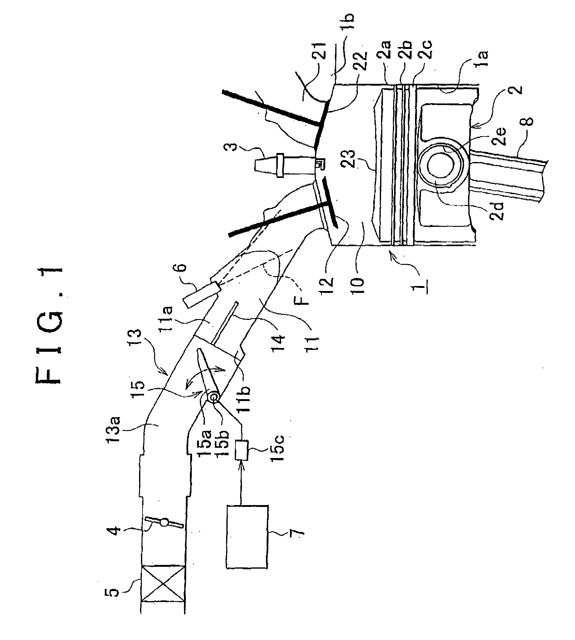
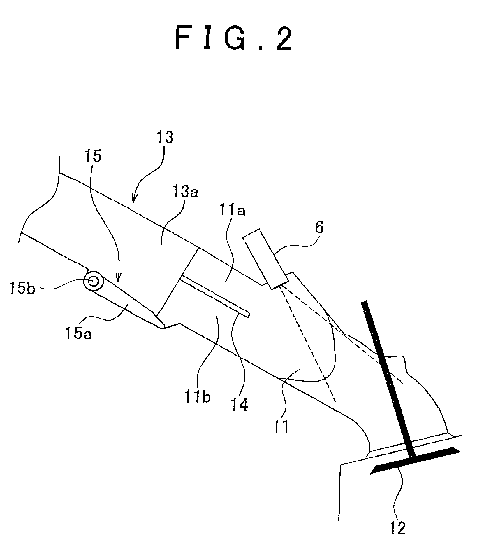
[0057]FIG. 1 is a sectional view showing the construction of a combustion chamber 10 of an engine (internal combustion engine) 1 and its surrounding components in accordance with this embodiment. As shown in FIG. 1, the engine 1 in accordance with this embodiment is a four-valve multi-cylinder gasoline engine including two intake valves 12 and two exhaust valves 22 for each cylinder. In FIG. 1, only one cylinder is shown, and only one intake valve 12 and one exhaust valve 22 are shown.

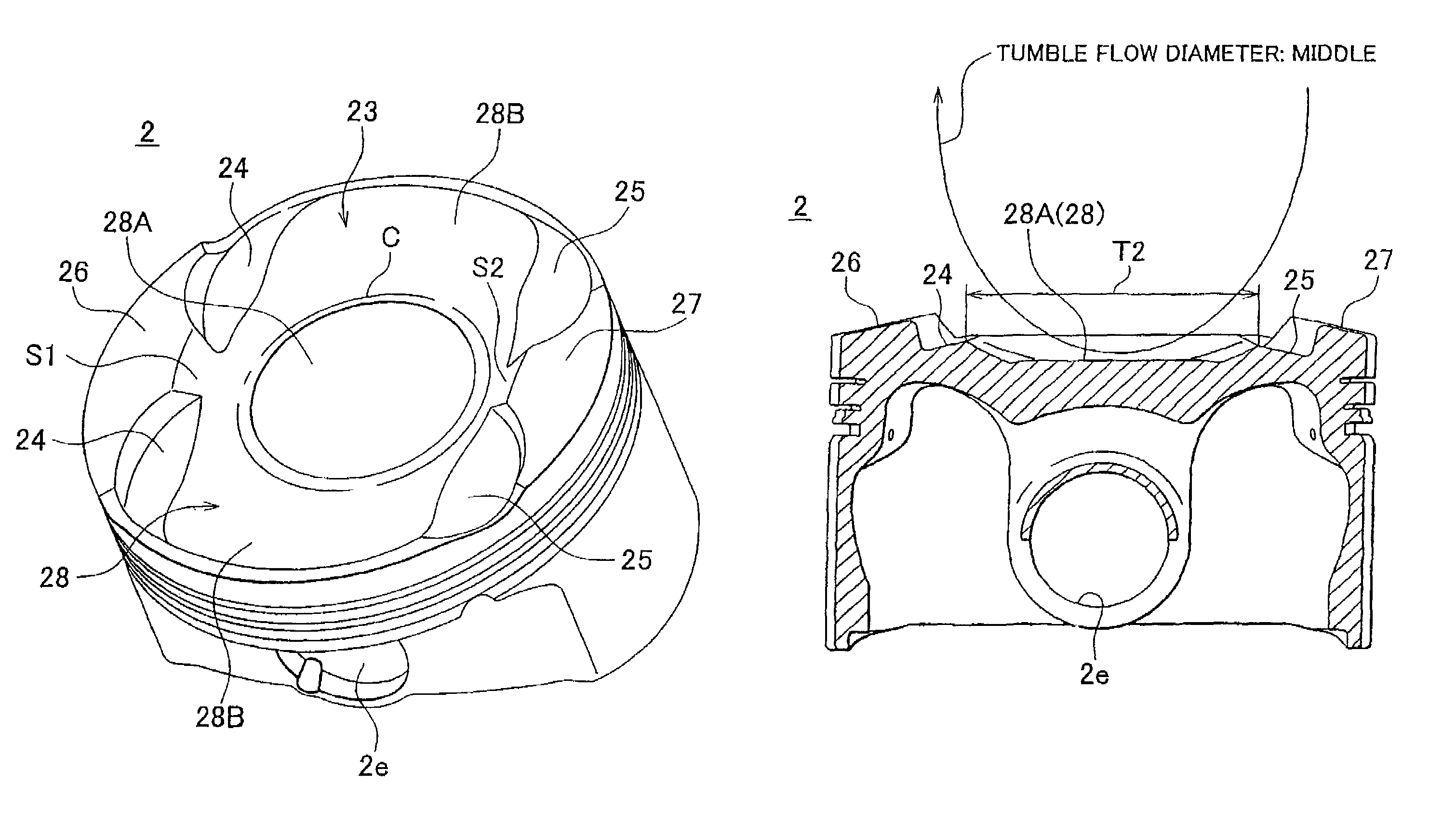
[0058]A piston 2 which can reciprocate vertically is provided in each cylinder 1a of the engine 1. The piston 2 is coupled to a crankshaft (not shown) via a connecting rod 8 so that reciprocating movement of the piston 2 is converted into rotation of ...


PUM


Abstract

A piston top surface (23) has a depression. A center region (28A) is formed at the center of the depression to secure the diameter of a center tumble flow to be large. A side region (28B) is formed on both sides of the piston top surface to generate a side tumble flow that is not influenced by a cylinder bore inner wall and has a flow line generally parallel to that of the center tumble flow.

Description

BACKGROUND OF THE INVENTION[0001]1. Field of the Invention[0002]The present invention relates to a piston for an internal combustion engine for an automobile or the like, and also to an internal combustion engine to which the piston is applied. More particularly, the present invention relates to an improvement in the shape of a depression formed in the top surface of a piston to maintain a tumble flow of intake air inside a cylinder.[0003]2. Description of the Related Art[0004]In conventional internal combustion engines (hereinafter occasionally referred simply to as “engines”) in which an air-fuel mixture is combusted in a combustion chamber to generate power, a tumble flow (vertical vortex flow) generated in a cylinder is effectively utilized to increase the combustion efficiency of fuel, and thus improves the output, the exhaust emission, the fuel consumption rate, and so forth. That is, the tumble flow agitates inside the cylinder to promote evaporation and atomization of fuel, ...

Claims


Application Information

Patent Timeline
Patent Type & Authority Patents(United States)
IPC IPC(8): F02F3/28
CPCF02B23/08F02B31/085F02F3/26F02B2275/48F02M35/021Y02T10/125Y02T10/146Y02T10/12
Inventor TACHIBANA, RYOJIYAMAGATA, MITSUMASATSUCHIYA, TOMIHISA
Owner TOYOTA JIDOSHA KK
Why Eureka
Try Eureka