Fluid dispenser

a dispenser and liquid technology, applied in the field of liquid dispensers, can solve problems such as the risk of losing the cap

Inactive Publication Date: 2010-12-28
APTAR FRANCE SAS
View PDF9 Cites 14 Cited by
  • Summary
  • Abstract
  • Description
  • Claims
  • Application Information

AI Technical Summary

Benefits of technology

[0004]An object of the present invention is to protect the dispenser endpiece by making it movable relative to the part from which it projects, in such a manner as to be able to retract it.
[0008]In an advantageous characteristic of the invention, the endpiece is connected to the actuator rod via a flexible hose. The hose makes it possible to interconnect, with a considerable degree of freedom, the end of the actuator rod of the dispenser member and the dispenser endpiece that is displaced simultaneously in turning and in radial translation. The end of the hose that is connected to the dispenser endpiece must follow a path that is substantially or partially helical. Consequently, it is necessary for the hose to present good deformability characteristics without kinking.

Problems solved by technology

However, this requires the user to remove the cap and put it back into place each time the dispenser is used.
There is also a risk of losing the cap.

Method used


Image

  • Fluid dispenser
  • Fluid dispenser
  • Fluid dispenser

Examples


first embodiment

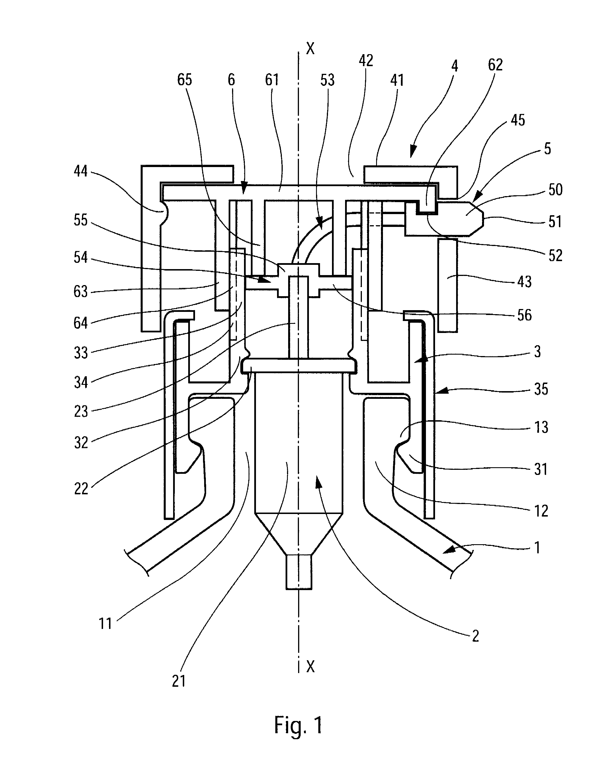
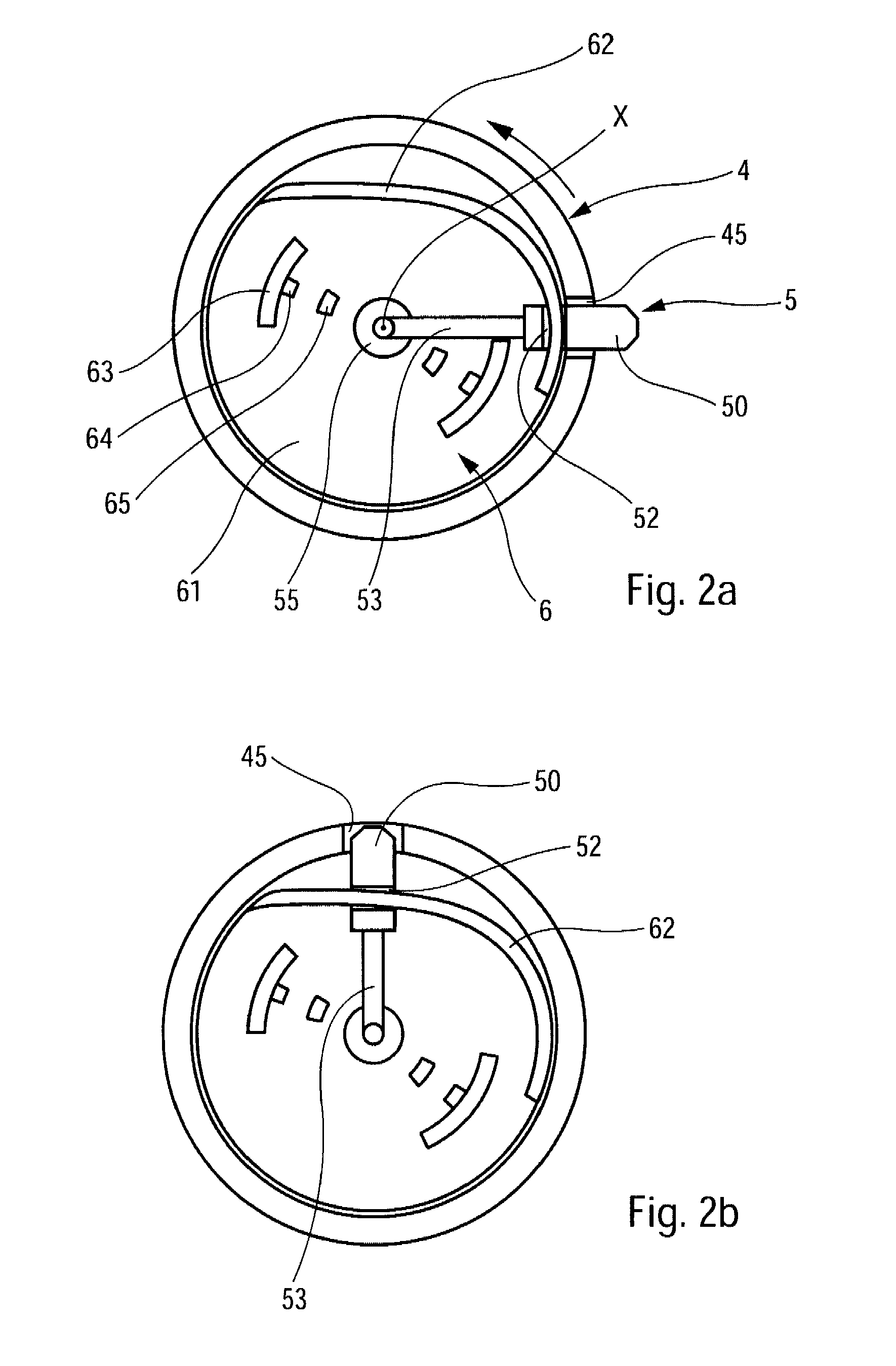
[0022]Reference is made firstly to FIGS. 1, 2a, and 2b in order to describe in detail the structure and the operation of a fluid dispenser constituting the invention. The dispenser comprises six component elements, namely: a fluid reservoir 1; a dispenser member 2, which can be a pump or a valve; a fastener ring 3 for fastening the pump or the valve on the receptacle; a pusher 4 on which the user can press so as to actuate the pump or the valve; a dispenser part 5; and a cam element 6. Most of these elements can be made by injection-molding plastics material.

[0023]The reservoir 1 comprises a reservoir body (not shown) which is terminated at its top end by a neck 12 defining an opening 11, putting the inside of the reservoir into communication with the outside. The neck 12 includes an annular shoulder 13 that is directed downwards. The shoulder is formed by annular reinforcement that projects radially outwards. This is a fairly conventional design for a reservoir in the fields of per...

second embodiment

[0036]In this second embodiment, it should be observed that the actuator member is distinct from the pusher, and that the cam element 6′ is not displaced axially. However, turning the actuator member 7 relative to the cam element 6′ makes it possible to displace the dispenser endpiece 50 along a substantially helical path, resulting in a combined rotary and radial displacement.

third embodiment

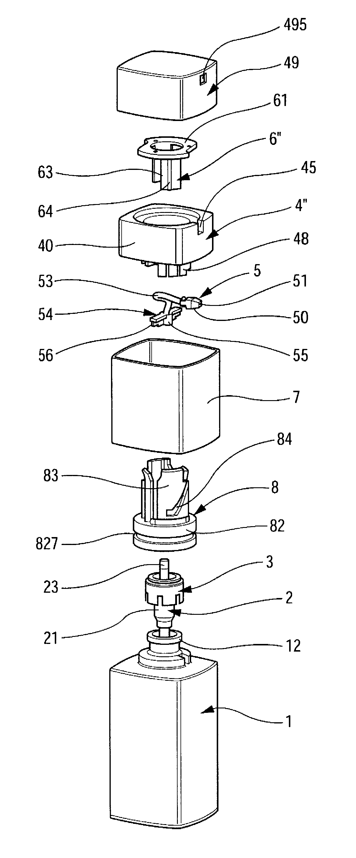
[0037]Reference is made below to FIGS. 4, 5a, and 5b in order to describe a more complex third embodiment of the invention. The dispenser comprises eight component elements, namely: a reservoir 1; a pump 2; a fastener ring 3; a ferrule 8, a rotary actuator member 7; a dispenser part 5; a pusher 4″ constituted by a body 40 and by a cover 49; and a cam element 6″.

[0038]The reservoir 1 includes a neck 12 in which the pump 2 is engaged. The fastener ring 3 makes it possible to fasten the pump 2 on the neck 12 in leaktight manner. The ferrule 8 is mounted stationary, both in turning and in axial displacement, on the ring 3 or on the reservoir 1. The ferrule 8 includes a base 82 forming a slide groove 827. Above the base 82, the ferrule 8 includes a bushing 83 that externally defines a second cam path 84, and that internally defines axial guide grooves (not shown). The second cam path 84 comprises a helical portion in the form of a screw thread, and an axial vertical portion that is conne...


PUM


Abstract

A fluid dispenser having: a fluid reservoir, a fluid dispenser member having actuator rod (23) that is displaceable down and up along an axis X, a pusher (4; 4; 4″) that displaces the actuator rod (23), a dispenser endpiece (50) defining a dispenser orifice (51), and a displacement mechanism (6, 4; 6′, 7; 6″, 7, 4″) that displaces the endpiece (50) both in turning about the axis X and in radial translation, the radial distance between the endpiece and the axis X varying as the endpiece turns about the axis X, such that the endpiece is displaceable between an extended position remote from the axis X and a retracted position close to the axis X.

Description

CROSS REFERENCE TO RELATED APPLICATION[0001]This application claims the benefit under 35 U.S.C. §119(e) of pending U.S. provisional patent application Ser. No. 60 / 899,001, filed Feb. 2, 2007, and priority under 35 U.S.C. §119(a)-(d) of French patent application No. FR-06.54737, filed Nov. 6, 2006.TECHNICAL FIELD[0002]The present invention relates to a fluid dispenser comprising: a reservoir; a dispenser member, such as a pump or a valve; a fastener ring for fastening the pump or the valve on an opening of the reservoir; a pusher that is axially displaceable so as to displace the actuator rod; and a dispenser endpiece defining a dispenser orifice. Such fluid dispensers are commonly used in the fields of perfumery, cosmetics, or even pharmacy.BACKGROUND OF THE INVENTION[0003]In the field of cosmetics, dispensers are often made with a projecting endpiece, e.g. in the form of a nozzle. The dispenser orifice is situated at the free end of the endpiece or nozzle. By means of the projectin...

Claims


Application Information

Patent Timeline
Patent Type & Authority Patents(United States)
IPC IPC(8): B67D3/00
CPCB05B11/3049B65D47/2012B05B11/0032B05B11/3059B65D83/22B65D83/56B05B11/3047B65D83/206B05B15/065B05B15/65B05B11/1049B05B11/106
Inventor MICHAUX, SEBASTIENBERTIN, ROMAIN
Owner APTAR FRANCE SAS
Why Eureka
Try Eureka