Faucet having leakproof effect

a faucet and leakproof technology, applied in the field of faucets, can solve the problems of inconvenience for users when operating the faucet, and achieve the effect of stabilizing the water pressure in the faucet body and saving user's energy

Inactive Publication Date: 2010-12-28
HUANG LI CHEN
View PDF5 Cites 18 Cited by
  • Summary
  • Abstract
  • Description
  • Claims
  • Application Information

AI Technical Summary

Benefits of technology

[0009]Another objective of the present invention is to provide a faucet, wherein the sealing gasket, the leakproof gasket, the first leakproof cap and the second leakproof cap of the control valve are tightly and closely located between the control shaft of the control valve and the through hole of the faucet body to seal the through hole of the faucet body so as to prevent the water from leaking from the through hole of the faucet body and to stabilize the water pressure in the faucet body.
[0010]A further objective of the present invention is to provide a faucet, wherein when the water flow stops, the stop gasket of the control valve is pushed by the restoring force of the restoring member of the control valve to detach from the flow channel of the sleeve to connect the flow channel of the sleeve to the receiving chamber of the sleeve so that the water flows outwardly from the water outlet port of the faucet body at a normal state, thereby facilitating the user operating the faucet.
[0011]A further objective of the present invention is to provide a faucet, wherein the control knob of the control valve is pushed by the restoring force of the restoring member of the control valve to return to the original state, thereby saving the user's energy.

Problems solved by technology

However, the O-ring between the first end of the control shaft and the through hole of the faucet body cannot seal the through hole of the faucet body efficiently, so that the water easily leaks outwardly from the through hole of the faucet body, thereby causing inconvenience to the user when operating the faucet.

Method used


Image

  • Faucet having leakproof effect
  • Faucet having leakproof effect
  • Faucet having leakproof effect

Examples


Embodiment Construction

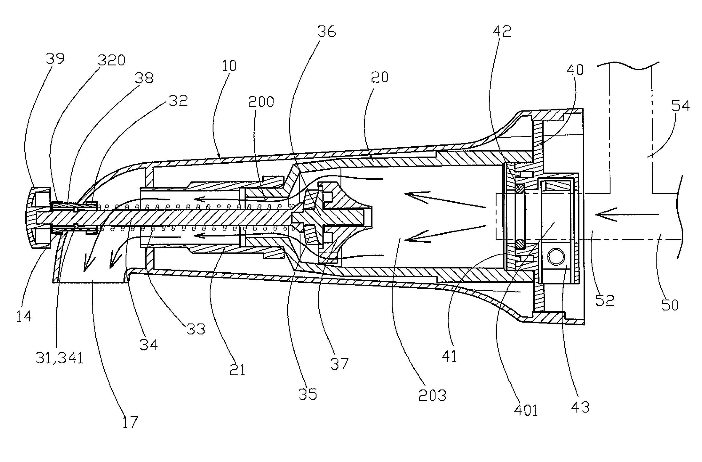
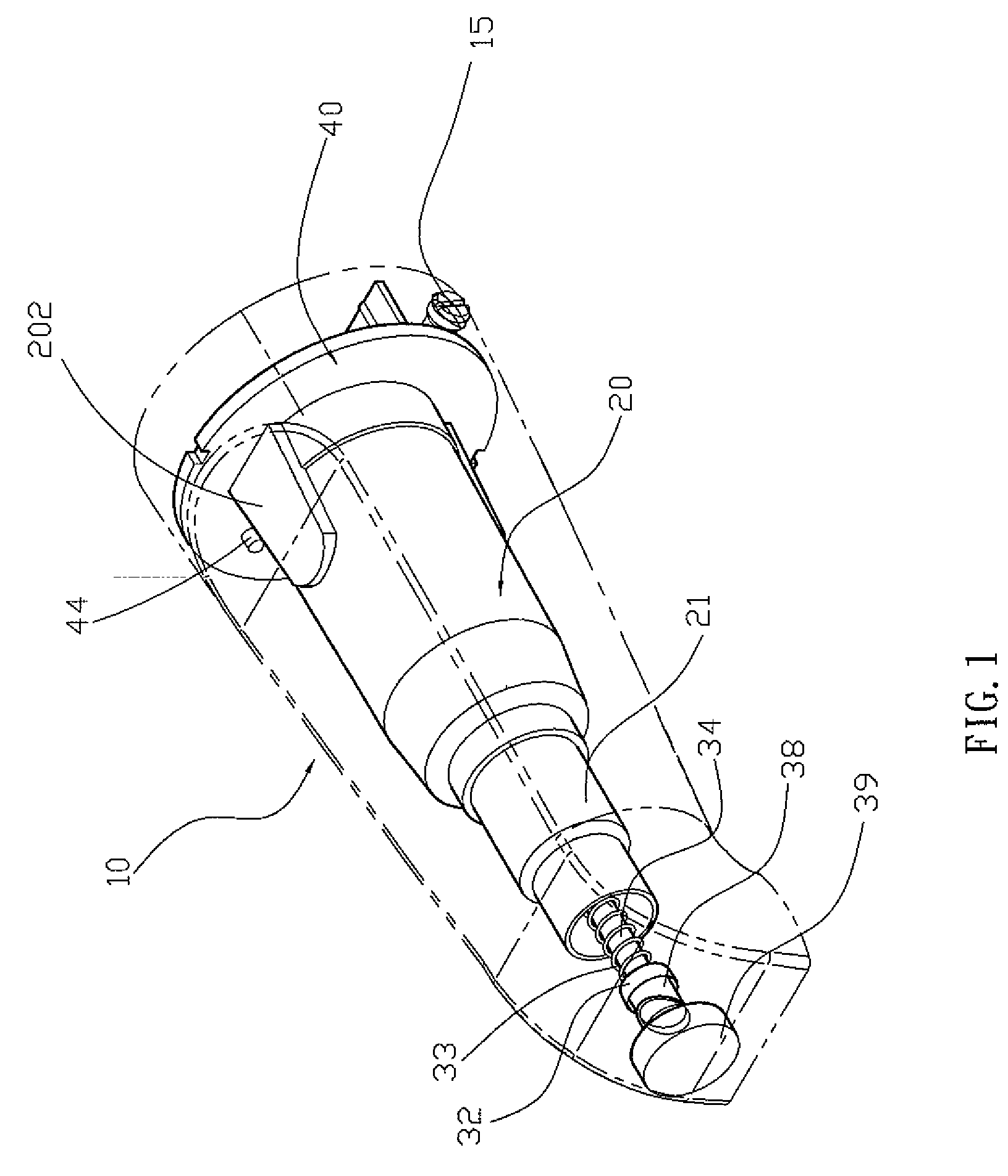
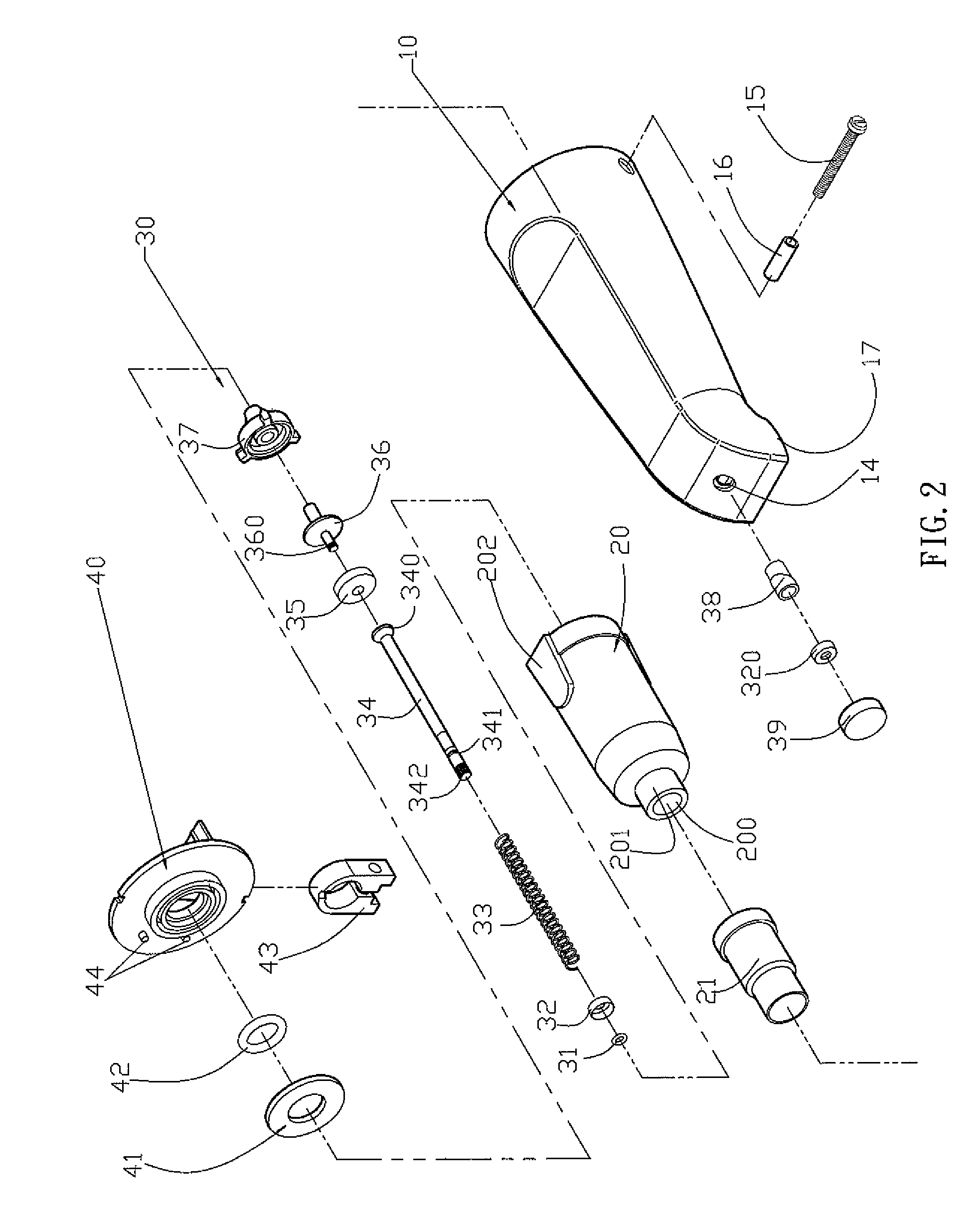
[0020]Referring to the drawings and initially to FIGS. 1-5, a faucet in accordance with the preferred embodiment of the present invention comprises a faucet body 10, a sleeve 20, a control valve 30, and a mounting seat 40.

[0021]The faucet body 10 has a first end provided with a through hole 14 and a water outlet port 17.

[0022]The sleeve 20 is mounted in a second end of the faucet body 10 and has a first end provided with a flow channel 200 connected to the through hole 14 and the water outlet port 17 of the faucet body 10 and a second end provided with a receiving chamber 203 connected to the flow channel 200. The first end of the sleeve 20 is provided with a protruding mounting post 201. The second end of the sleeve 20 has a periphery provided with two radially opposite protruding limit edges 202. An extension sleeve 21 is mounted in the faucet body 10 and has a first end mounted on the mounting post 201 of the sleeve 20 and a second end connected to the through hole 14 and the wat...


PUM


Abstract

A faucet includes a faucet body, a sleeve, a control valve, and a mounting seat. The control valve includes a control shaft, a stop gasket, a retaining member, a leakproof gasket, a sealing gasket, a first leakproof cap, a second leakproof cap, a control knob, and a restoring member. Thus, the sealing gasket, the leakproof gasket, the first leakproof cap and the second leakproof cap of the control valve are tightly and closely located between the control shaft and the through hole of the faucet body to seal the through hole so as to prevent the water from leaking from the through hole and to stabilize the water pressure in the faucet body.

Description

BACKGROUND OF THE INVENTION[0001]1. Field of the Invention[0002]The present invention relates to a faucet and, more particularly, to a faucet that is connected to a shower head.[0003]2. Description of the Related Art[0004]A conventional faucet comprises a faucet body, a sleeve, and a control valve. The faucet body has a first end provided with a through hole and a water outlet port. The sleeve is mounted in a second end of the faucet body and has a first end provided with a flow channel connected to the through hole and the water outlet port of the faucet body and a second end provided with a receiving chamber connected to the flow channel. The control valve is mounted in the faucet body and the sleeve and includes a control shaft movably mounted in the faucet body and the sleeve and having a first end extending through the through hole of the faucet body and a second end extending into the receiving chamber of the sleeve, a stop member secured on the second end of the control shaft...

Claims


Application Information

Patent Timeline
Patent Type & Authority Patents(United States)
IPC IPC(8): F16K1/12
CPCE03C1/023F16K1/12F16K41/04Y10T137/9464Y10T137/2685
Inventor HUANG, LI-CHEN
Owner HUANG LI CHEN
Why Eureka
Try Eureka