Dust collection unit for vacuum cleaner

a vacuum cleaner and dust collection technology, applied in the field of vacuum cleaners, can solve the problems of difficult cleaning of the filter, inconvenient reuse of paper filters, and still remains of periodic cleaning filters, so as to achieve the effect of effectively removing small foreign objects and providing the convenience of use to users

Inactive Publication Date: 2010-12-28
LG ELECTRONICS INC
View PDF55 Cites 41 Cited by
  • Summary
  • Abstract
  • Description
  • Claims
  • Application Information

AI Technical Summary

Benefits of technology

[0012]Another object of the present invention is to provide a dust collection unit for a vacuum cleaner, which can effectively filter small foreign objects as well as large foreign objects, thereby improving the dust collection efficiency.
[0018]According to the present invention, the dust collection efficiency is improved.
[0019]In addition, a variety of cyclone airflows are possibly generated and no filter member is provided, thereby effectively removing small foreign objects as well as large foreign objects and providing the convenience in use to a user.
[0020]Furthermore, since the airflow system is effectively designed, the airflow resistance can be reduced to improve the dust collection efficiency.
[0021]In addition, the collected foreign objects can be exhausted by opening a lower cover, thereby further improving the user's convenience.

Problems solved by technology

However, since it is inconvenient to reuse the paper filter and it is difficult to clean the filter, a cyclone type vacuum cleaner has been recently proposed.
However, when the filter member formed of a porous filter is combined with the cyclone unit, the problem of periodically cleaning the filter still remains.
When the foreign objects clogs the porous filter, an airflow rate is reduced, thereby deteriorating the operational efficiency of the vacuum cleaner.
In this case, an overall size of the dust collection unit increases, thereby undesirably increasing an overall volume of the vacuum.
Therefore, it is not easy for the user to handle the vacuum cleaner.

Method used


Image

  • Dust collection unit for vacuum cleaner
  • Dust collection unit for vacuum cleaner
  • Dust collection unit for vacuum cleaner

Examples


Embodiment Construction

[0030]Reference will now be made in detail to the preferred embodiments of the present invention, examples of which are illustrated in the accompanying drawings. Wherever possible, the same reference numbers will be used throughout the drawings to refer to the same or like parts.

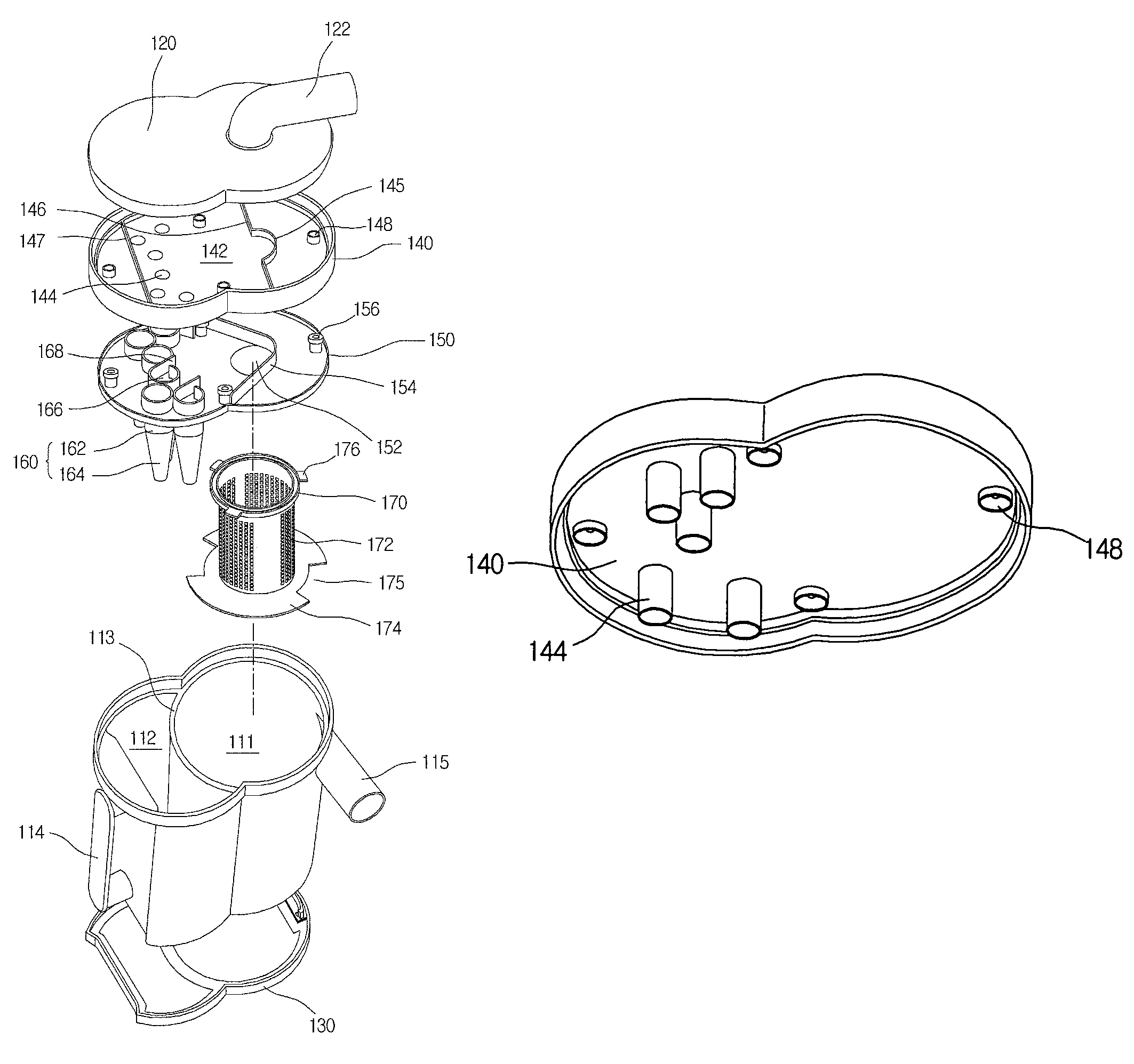
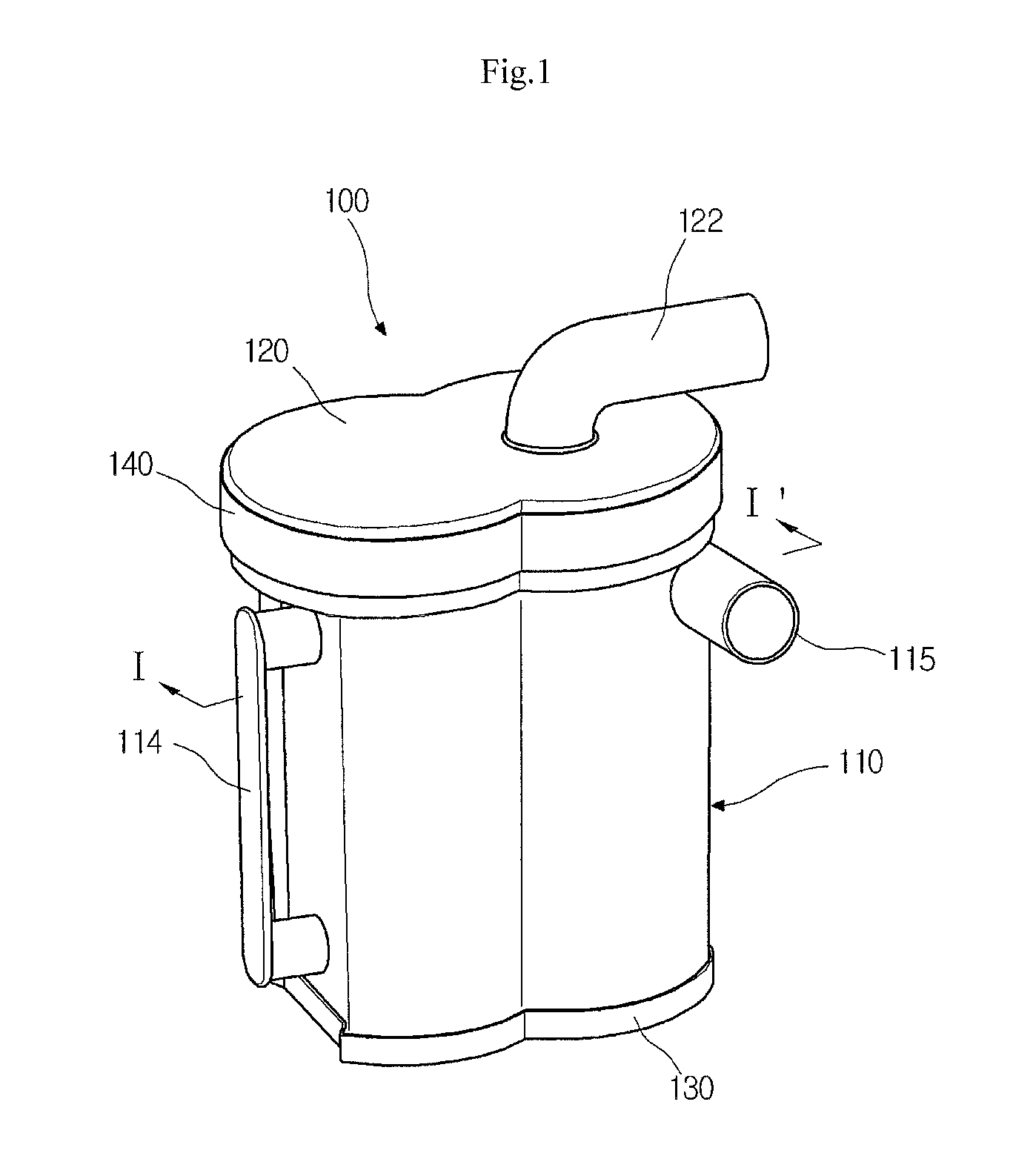
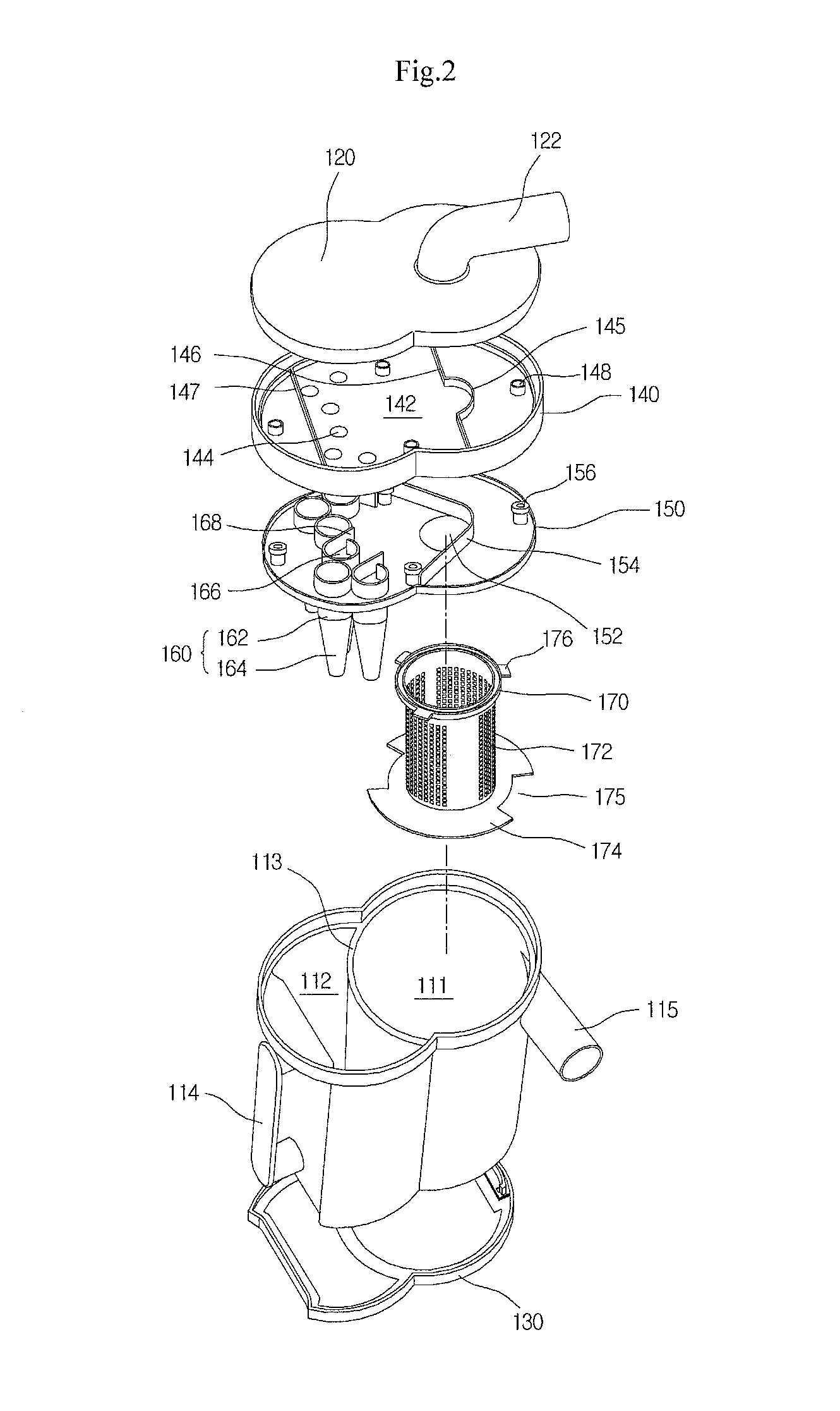
[0031]FIGS. 1 and 2 show a dust collection unit according to an embodiment of the present invention.

[0032]Referring to FIGS. 1 and 2, the inventive dust collection unit includes a dust collection container 110 having an 8-shaped section.

[0033]An inner space of the dust collection container 110 is divided into first and second dust collection chambers 111 and 112 that are arranged in a line and designed to respectively receive first and second dust collection parts that will be described later.

[0034]A barrier 113 is formed between the first and second dust collection chamber 111 and 112. The barrier 113 is curved toward the second dust collection chamber 112 such that the first collection chamber 111 can be f...


PUM

PropertyMeasurementUnit
surface areaaaaaaaaaaa
diameteraaaaaaaaaa
shapeaaaaaaaaaa

Abstract

A dust collection unit for a vacuum cleaner includes a first dust collection part for filtering foreign objects in air, a second dust collection part for filtering foreign objects in the air that has passed through the first dust collection part, and a dust collection container having first and second dust collection chambers that correspond to the first and second dust collection parts, respectively. The first and second dust collection chambers store the foreign objects filtered by the respectively first and second dust collection parts in a state where parts of the respective first and second dust collection parts are received in the respective first and second dust collection chambers and the first and second dust collection chambers are provided in a line.

Description

BACKGROUND OF THE INVENTION[0001]1. Field of the Invention[0002]The present invention relates to a vacuum cleaner, and particularly, to a dust collection unit OF a vacuum cleaner, which has a first dust collection part for filtering relatively large foreign objects and a second dust collection part for filtering relatively small foreign objects, the first and second dust collection parts being separated from each other. In addition, the present invention further relates to a dust collection unit for a vacuum cleaner, which is designed in a proper size and shape so that it can be easily mounted in a main body of the vacuum cleaner.[0003]2. Description of the Related Art[0004]A vacuum cleaner is used to clean a room or other spaces by sucking air containing foreign objects and filtering the foreign object using vacuum pressure generated therein. In order to filter the foreign objects contained in the sucked air, a dust collection unit is provided in the vacuum cleaner and a paper filt...

Claims


Application Information

Patent Timeline
Patent Type & Authority Patents(United States)
IPC IPC(8): B01D50/00
CPCA47L9/1625A47L9/1641A47L9/1683B04C5/103B04C5/185B04C5/26B04C2009/004A47L9/10
Inventor PARK, TAE JINKIM, SEONG YONG
Owner LG ELECTRONICS INC
Why Eureka
Try Eureka