Method for molding vehicular wheel rim

a technology for vehicular wheels and rims, which is applied in the direction of tooth capping, manufacturing tools, dental surgery, etc., to achieve the effects of convenient curling, efficient molding, and preventing buckling

Active Publication Date: 2011-01-04
DAIDO KOGYO CO LTD
View PDF6 Cites 1 Cited by
  • Summary
  • Abstract
  • Description
  • Claims
  • Application Information

AI Technical Summary

Benefits of technology

[0015]The invention allows the wheel rim to be molded efficiently from the cylindrical material by successively applying the electromagnetic molding step and the curling step and prevents the buckling from occurring at the drop portion of the cylindrical body by restraining the outer periphery of the drop portion by the buckling preventing die in the curling step carried out by pressing. Then, as for the cylindrical material having the equal thickness, while the thickness is kept relatively thick at the drop portion, it is thin at the side portions by the enlargement of the electromagnetic molding step. The thin both side portions may be readily curled by relatively low compression force in the axial direction, allowing the vehicular wheel rim to be manufactured at high precision in combination with the restraint of the outer periphery of the drop portion by the buckling preventing fixture.
[0016]Still more, when the electromagnetic molding die is used as the buckling preventing die, it becomes possible to cut the equipment costs and to simplify the molding steps because it is not necessary to replace the electromagnetic molding die with the buckling preventing die.
[0017]The wheel rim manufactured by the manufacturing method of the invention has the thick drop portion that junctions with the disk and the relatively thin both side portions, so that it becomes possible to lighten its weight, even though it bears the large load, and to cut the number of processing steps and to improve product performance because the rim has no junction. Further, because the disk is fixed to the drop portion by welding or the like, it becomes possible to design the disk solely and to have an excellent decorative design. Still more, it allows highly accurate products to be obtained.

Problems solved by technology

However, there has been a problem in pressing a curling die against the edges of the side portions to bend and curl the edges in an external direction (external curling process) in a curling process after the electromagnetic molding that the drop portion of the cylindrical body buckles due to the pressure in the axial direction of the curling die.

Method used


Image

  • Method for molding vehicular wheel rim
  • Method for molding vehicular wheel rim
  • Method for molding vehicular wheel rim

Examples


embodiment

(1) Standard Name: Wheel Rim specified by JATMA (Japan Automobile Tyre Manufacturers Association)

(2) Nominal Size of Rim: 10×5.5 AT

(3) Material: A6063-O material

(4) Workpiece: Cylindrical material molded by extrusion molding

[0036]Outer Diameter: (φ198.8 [mm]

[0037]Thickness (plate thickness): 2.5 [mm]

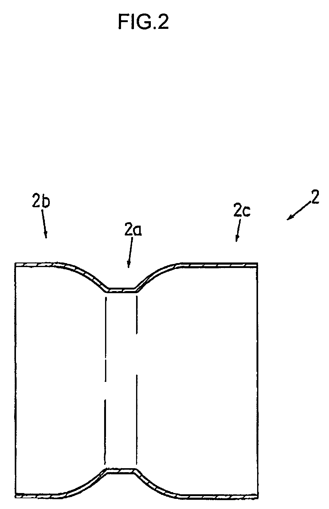
(5) State of Cylindrical Body caused by Electromagnetic Molding Step

[0038]Diameter of Edge of Enlarged Tube (both side portions): (φ250 [mm]

[0039]Thickness of Edge of Enlarged Tube: 2.1 [mm]

[0040]Rate of Enlargement of Tube: about 25%

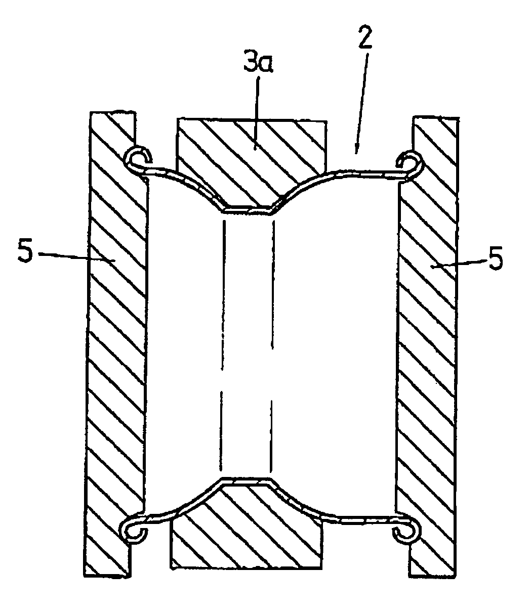
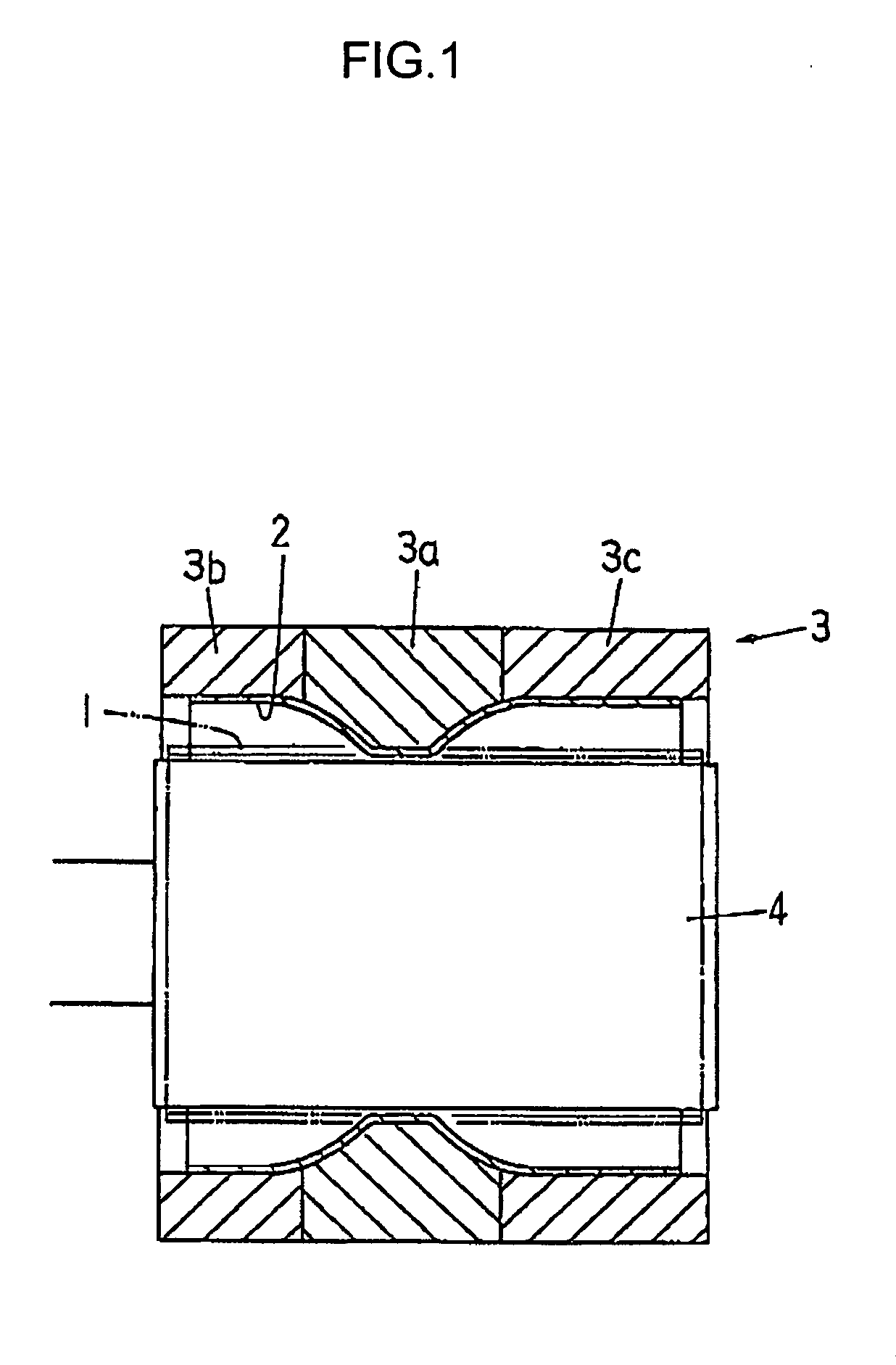
(6) Processing Conditions in Curling Step

[0041]Example 1: Maximum Load 95 [KN]

[0042]Machining Speed 20 [mm / min.]

[0043]Example 2: Maximum Load 100 [KN]

[0044]Machining Speed 10 [mm / min.]

(a) Present Invention

[0045]Composition of Parts: 2 pieces (cylindrical body+disk)

[0046]Thickness of Plate Member (drop portion): about 2.5 [mm]

[0047]Weight of Wheel: about 1450 [g]

(b) Spinning

[0048]Composition of Parts: 2 pieces

[0049]Thickness of Plate Member: about 3.0 [mm]

[00...


PUM

PropertyMeasurementUnit
diameteraaaaaaaaaa
timeaaaaaaaaaa
outer diameteraaaaaaaaaa

Abstract

A method prevents a cylindrical body from buckling in externally curling edges of both side portions by pressing curling dies in an axial direction after molding the cylindrical body having a drop portion whose outer diameter is small and two side portions whose outer diameter is large by enlarging a cylindrical material made of aluminum alloy by electromagnetic molding. In curling the edges of the side portions, a buckling preventing die restrains an outer periphery of the drop portion of the cylindrical body. Because the buckling preventing die receives the axial compression force of the curling dies, it can prevent the cylindrical body from buckling and deforming. The buckling preventing die is what a split die disposed on the side of an outer periphery of the cylindrical material in the electromagnetic molding is used as.

Description

BACKGROUND OF THE INVENTION[0001]1. Field of the Invention[0002]The present invention relates to a method for molding a vehicular wheel rim made of a metal plate or protruded member.[0003]2. Related Art[0004]Japanese Patent Laid-Open No. 2005-95982 Gazette (US2005091850A1) describes a method for manufacturing a wheel for use in passenger cars, trucks, buggies and the like. It then discloses a method for molding a wheel rim by disposing an electromagnetic molding die whose inner face serves as a molding face at an outer peripheral side of a cylindrical material made of aluminum alloy, disposing an electromagnetic molding coil at an inner peripheral side of the cylindrical material, charging electrical energy to the electromagnetic molding coil in this state to enlarge and press the cylindrical material against the molding face of the molding die to mold a cylindrical body having a drop portion whose outer diameter is small and both side portions whose outer diameter is larger than th...

Claims


Application Information

Patent Timeline
Patent Type & Authority Patents(United States)
IPC IPC(8): B21F43/00B23P13/04A61C5/02A61C3/08
CPCB21D19/12B21D53/30Y10T29/4994Y10T29/49375Y10T29/53083Y10T29/49524Y10T29/49803Y10T29/49531
Inventor IMAMURA, YOSHIHAYASATO, JUNICHIMASUMOTO, DAIGOMOTODE, KATSUHIRO
Owner DAIDO KOGYO CO LTD
Why Eureka
Try Eureka