
Wall panel system including a pivot lock

a technology of pivot lock and wall panel, which is applied in the direction of wing accessories, separation processes, filtration separation, etc., can solve the problems of multiple operations, significant disadvantages of the independent lock mechanism of the fixing and locking unit, etc., and achieve the effect of simple operation

Active Publication Date: 2011-01-04
C R LAURENCE
View PDF10 Cites 35 Cited by
  • Summary
  • Abstract
  • Description
  • Claims
  • Application Information

AI Technical Summary

Benefits of technology

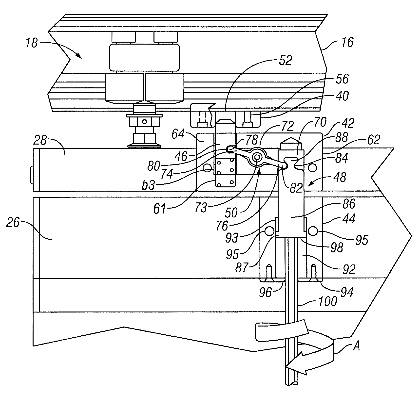
"The present invention provides a pivot lock and related method for a door lock system that allows for easy conversion between sliding and pivoting configurations. The pivot lock includes a first and second lock member coupled by a coupling mechanism that creates synchronized motion between the lock members. The lock members are engagement pins that selectively extend and retract into housings, or slidably and threadably engage bores in the housings. A biasing mechanism can be used to move the lock members into their predetermined positions. The wall panel system includes a track and a wall panel assembly with a pivot lock and a retractable floor anchor. The pivot lock allows for easy conversion between sliding and pivoting configurations, and the wall panel assembly includes a pivot rail and a door closer assembly for added security."

Problems solved by technology

The independence of the lock mechanisms provides a significant disadvantage for the fixing and locking unit because a user is required to employ the proper sequence of locking and unlocking the unit in order to avoid damaging the panel.
A significant disadvantage of the known lock mechanisms is that they require multiple operations that must be performed by a user in proper order to operate correctly and to avoid damaging the wall panel.

Method used


Image

  • Wall panel system including a pivot lock
  • Wall panel system including a pivot lock
  • Wall panel system including a pivot lock

Examples


Embodiment Construction

[0022]In the following paragraphs, the present invention will be described in detail by way of example with reference to the accompanying drawings. Throughout this description, the preferred embodiments and examples shown should be considered as exemplars, rather than as limitations on the present invention. As used herein, the “present invention” refers to any one of the embodiments of the invention described herein, and any equivalents. Furthermore, reference to various aspects of the invention throughout this document does not mean that all claimed embodiments or methods must include the referenced aspects.

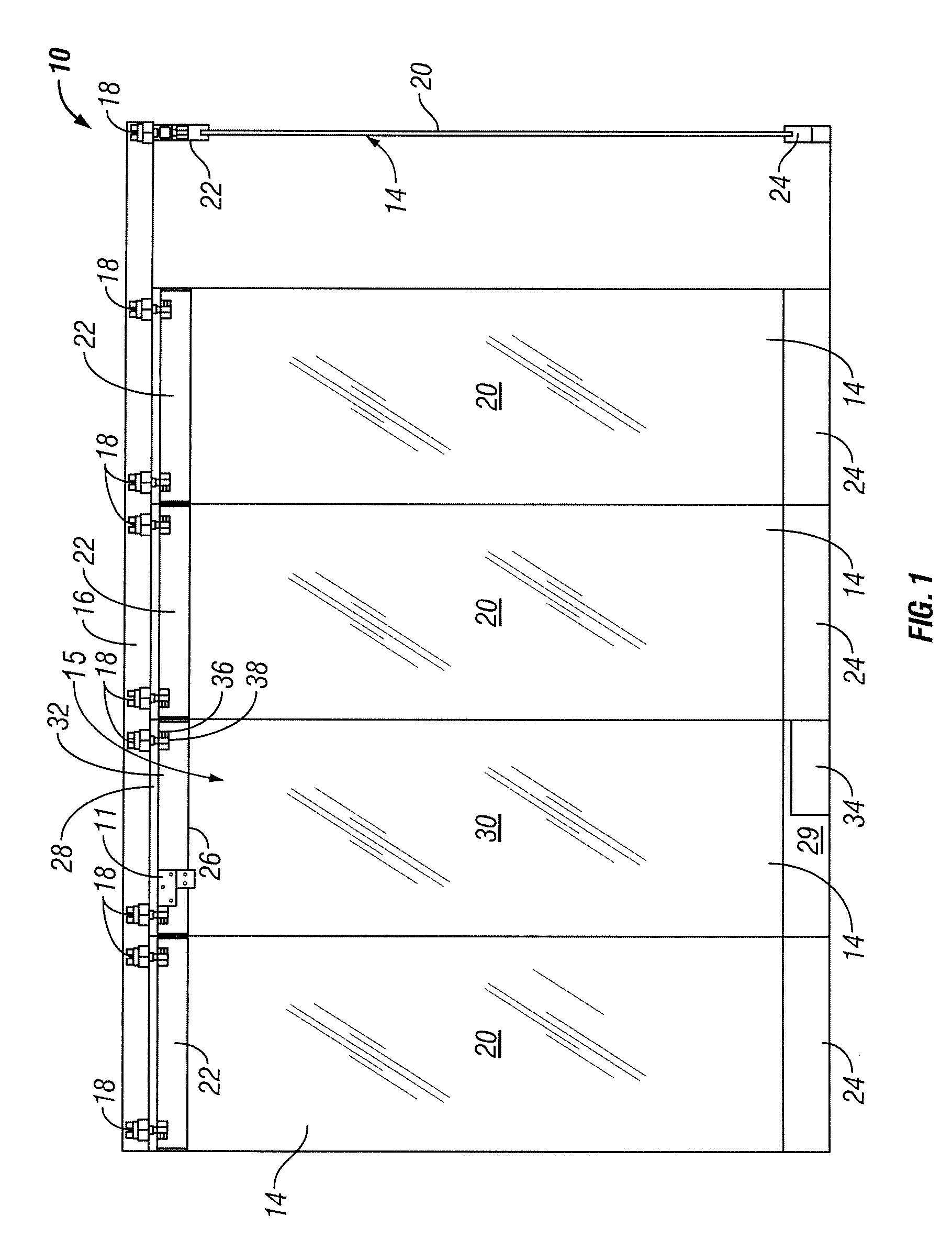
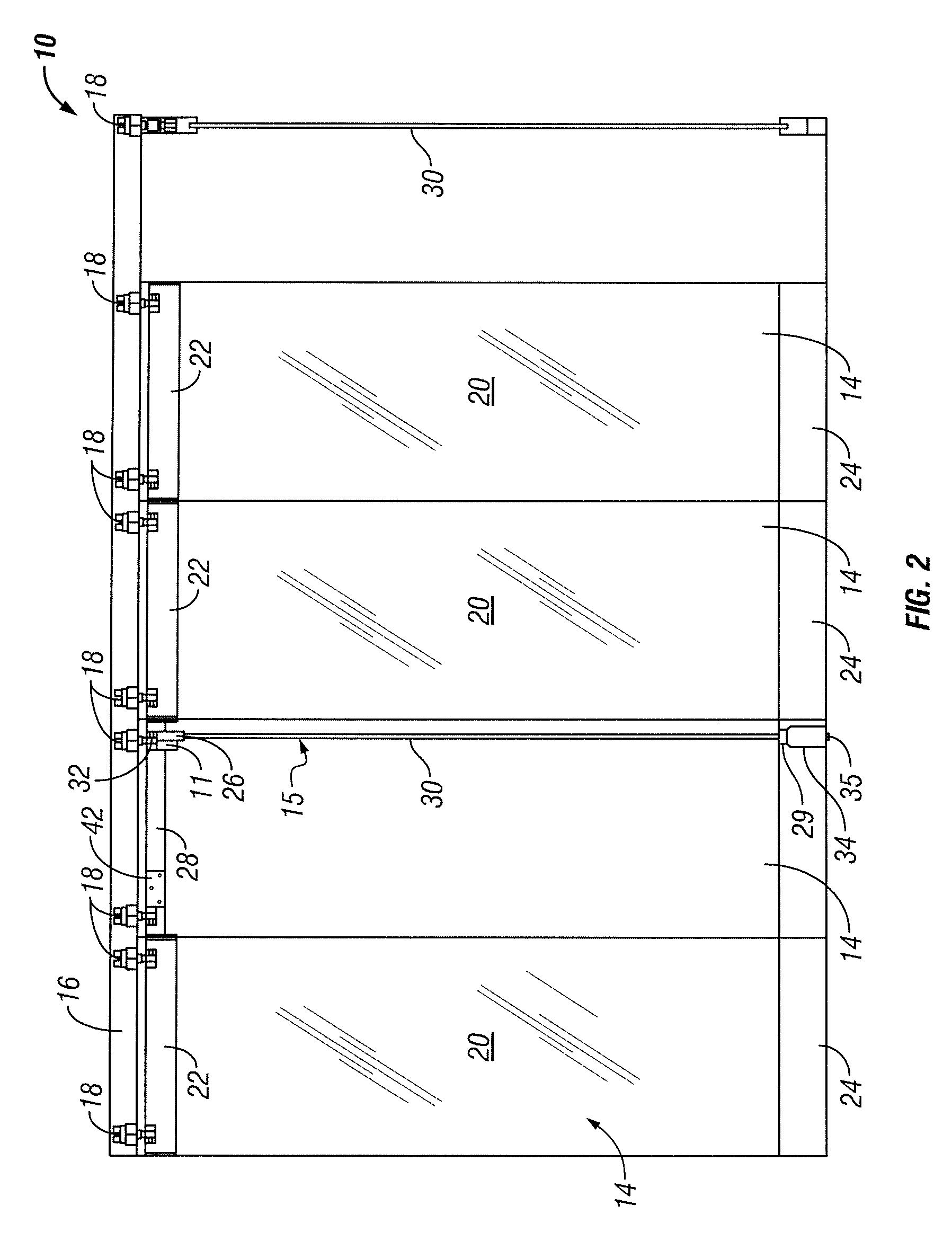
[0023]Referring first to FIGS. 1-3, a wall panel system 10 is described in which a pivot lock mechanism 11 is utilized. In general, pivot lock mechanism 11 allows a pivoting wall panel assembly 15 of wall panel system 10 to be converted between a sliding / rolling configuration and a pivoting configuration. In particular, pivot lock mechanism 11 includes a first lock member that ...


PUM

PropertyMeasurementUnit
lengthaaaaaaaaaa
forceaaaaaaaaaa
areaaaaaaaaaaa

Abstract

A wall panel system includes a sliding wall panel assembly that includes a pivot lock for converting the wall panel assembly between a sliding configuration and a pivoting configuration. The pivot lock includes a first lock member that is configured to selectively prevent translation of the wall panel assembly along a track and a second lock member that is configured to selectively prevent pivoting of at least a portion of the wall panel assembly relative to the track.

Description

FIELD OF THE INVENTION[0001]The present invention relates to movable wall panel systems and, in particular, to wall panel systems that include pivoting wall panel assemblies.BACKGROUND OF THE INVENTION[0002]Movable wall panels are often used to divide an area into two or more regions. For example, movable wall panels are employed in schools, hotels, and convention centers to divide a large room into two or more smaller rooms. Another common use of movable wall panels is the formation of individual shop fronts within a mall. Clear glass panels are typically stored during business hours to produce a wide-open storefront, and are disposed in front of the storefront during off-business hours while permitting the viewing of merchandise. Alternatively, the clear glass panels may be disposed in front of the storefront during business hours if desired, and a single panel may be configured to pivot to provide access, for example during inclement weather.[0003]Movable wall panel systems typic...

Claims


Application Information

Patent Timeline
Patent Type & Authority Patents(United States)
IPC IPC(8): E05D15/22E05D15/58
CPCE04B2/827E05B35/008E05B65/0085E05C1/02E05D15/58E05Y2800/22E05Y2900/142E05D15/0604E05Y2201/22E05Y2600/62E05D2015/587Y10T292/0969Y10T292/0977
Inventor SPRAGUE, GARY
Owner C R LAURENCE
Learn More