Container and removable closure cap with venting feature

a technology of closure cap and container, which is applied in the field of containers, can solve the problem of not being able to remove the cap from the container, and achieve the effect of reducing the sealing pressur

Active Publication Date: 2011-01-04
DAYTON SYST GRP
View PDF8 Cites 18 Cited by
  • Summary
  • Abstract
  • Description
  • Claims
  • Application Information

AI Technical Summary

Benefits of technology

[0018]Assuming a container is filled, and its cap is in place on the container neck with cap lugs engaged under all of the neck lugs, when the cap is subjected to an initial opening motion, a certain one (or ones) of the cap lugs will progress onto the venting portion(s) of the neck lugs which have such portions, and the internal pressure in the container will raise part of the cap in a region corresponding to that venting portion. This releases or substantially reduces the sealing pressure and a vent region or path is formed between a part of the cap periphery and the seal, and extending down between the inside of the cap and the container neck. The stop portions depending from the ends of the venting neck portion(s) provide a rotational limit to further cap rotation, while venting continues. Normally, this venting occurs rapidly, in a fraction of a second.
[0019]In the case of a container product packed under vacuum, differential pressure acting on the area of the cap within the seal will hold the cap in place, but the cap lugs will still be pressing against the neck lugs. As the cap is rotated, the seal will remain against and slide around the mouth of the container. Continued rotation will bring at least one of the cap lugs into alignment with a space between the neck lugs and into engagement with a lifting lug portion on the next neck lug. As the cap rim rises during rotation, the cap lug will transition over the upper surface of the lifting lug portion of the next neck lug. Then further cap rotation will force the portion of the seal adjacent to such cap lug to separate form the rim of the dispensing opening, thereby overcoming the force of the negative pressure within the container, and venting the container interior to ambient pressure.
[0021]Thus the invention provides unique and versatile containers for fluids, particularly for beverages, wherein various bottles or can bodies are provided with a special end including a neck with a dispensing opening, a special neck-like lug formation on the neck below the dispensing opening, a reclosable cap having a lug formation which will interlock with the neck-like lug formation on the neck. A seal structure, preferably on the cap interior, surrounds the dispensing opening in positive contact with the cap seal and maintains product under desired pressure or vacuum in the container.
[0022]In the metallic can body version of the invention, the neck or spout can be part of an end which can be attached to a can body by a seam between the bottom of the end below the neck and the rim of the can body, or such neck can be formed integrally with the can body. In the glass or plastic bottle version, the neck can be an integral part of a bottle or jar, including a seal surface around the dispensing opening at the top of the neck. The basic design and function of the lugged cap closure system is the same in both versions. Each version also includes a relatively large dispensing opening which is comfortable to someone drinking directly from the container. This novel cap and neck construction will also provide a neck with a cap that is not only reclosable but resealable.

Problems solved by technology

These neck lugs, normally at least three, cooperate with cap lugs to provide for a slightly opened position of the cap by which the seal is sufficiently released to vent the container, through the dispensing opening, but the cap is not removable from the container without further manual manipulation of the cap to a fully released location.

Method used


Image

  • Container and removable closure cap with venting feature
  • Container and removable closure cap with venting feature
  • Container and removable closure cap with venting feature

Examples


Embodiment Construction

Pressure Venting

[0038]The principal feature of the invention is a reclosable cap and cooperating neck lugs on the neck of the container, which feature can be applied to various containers, for example cans or bottles, made from different materials.

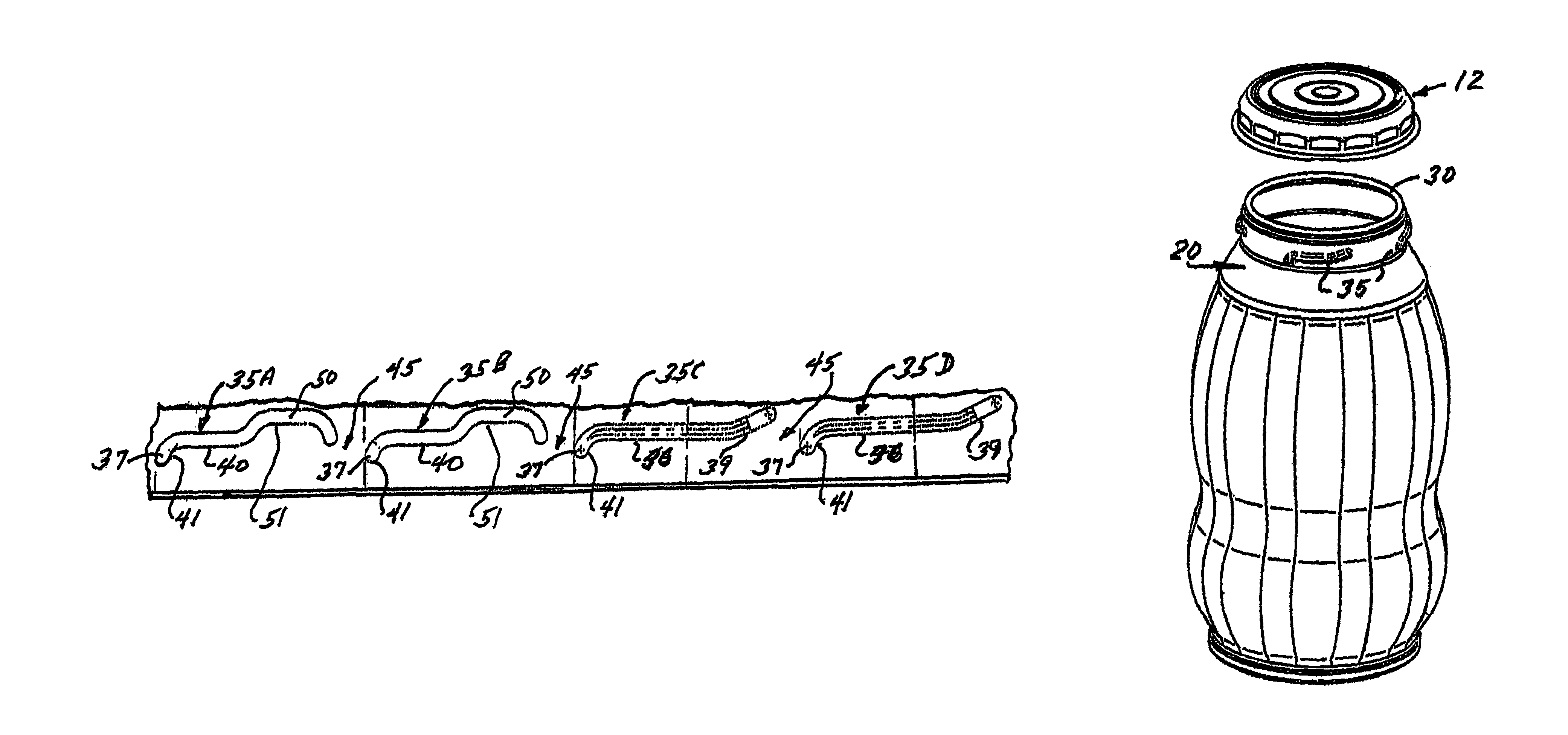
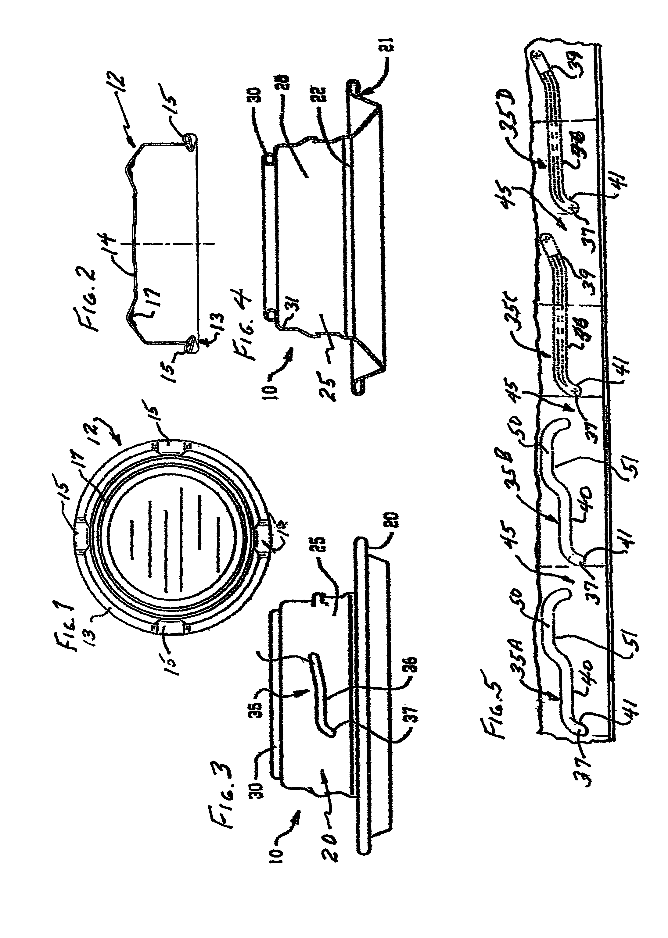
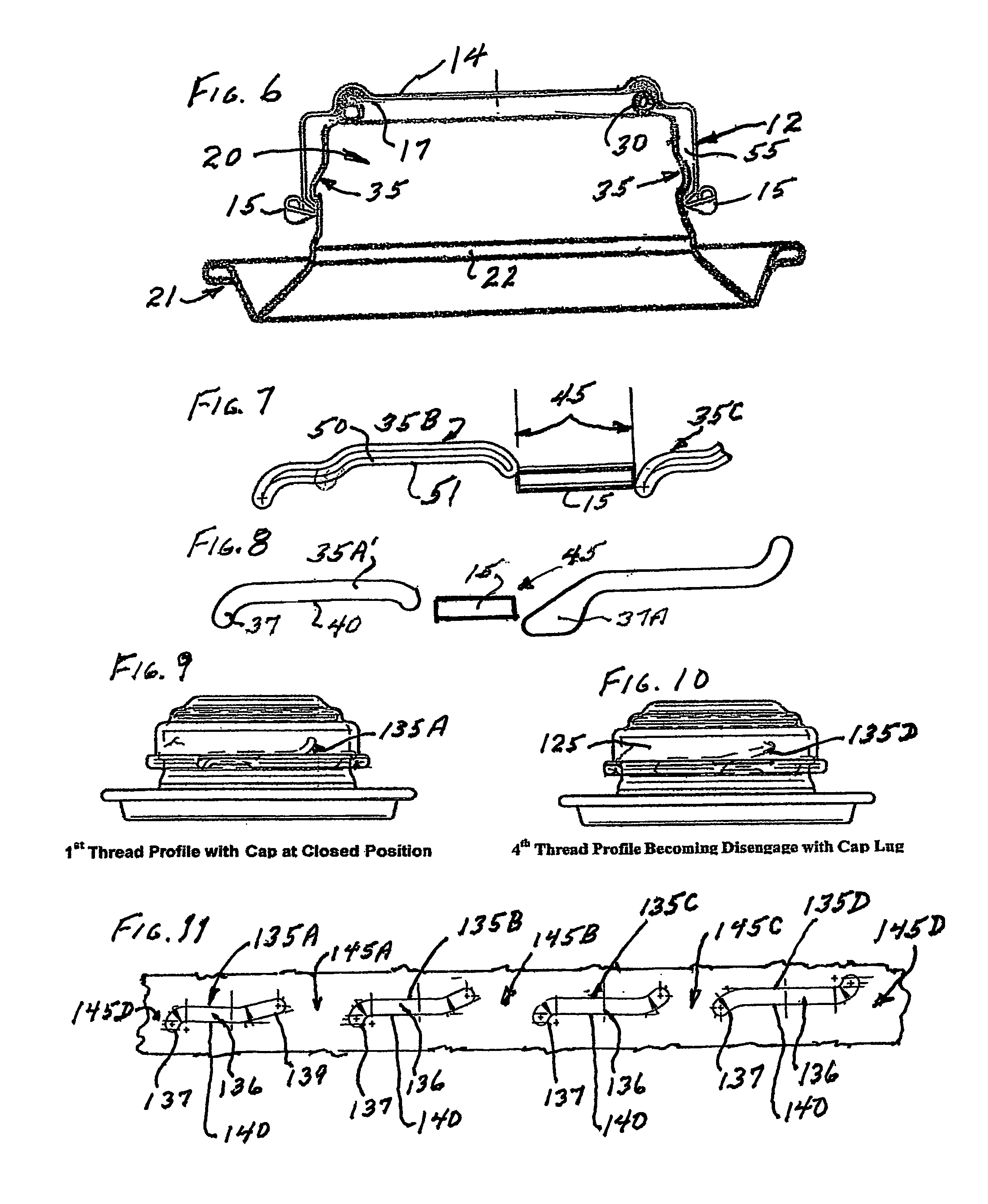
[0039]Dimensions, where shown, are for the purpose of explanation and are not limitations on the scope of the invention. The container end of the present invention, as executed in metal (preferably aluminum), is comprised of two major parts, a neck structure 10 (FIGS. 3 and 4), and a cap member 12 (FIGS. 1 and 2). The cap is in the general form of an inverted cup, including an outwardly curled lower rim 13 depending from the top panel 14 of cap member 12. Four cap lugs 15 are formed 90° apart on rim 13, and the interior surface beneath the top of the cap includes a seal member 17. As will be noted in FIG. 1 the cap lugs 15 are tapered to a smaller inner end as they extend generally radially inward from rim 13.

[0040]Referring to FIGS. 3 and...


PUM


Abstract

A resealable can end is provided including a neck (10) and a cooperating cap member (12) which can be sealed onto and removed from the neck, and is capable of containing product under pressure or vacuum if desired. This end may be added, by convention seaming methods, such as roll seaming or by appropriate adhesive, to a container body, or may be formed integrally with container bodies. The venting feature of the end will achieve a controlled release of differential internal-to-ambient pressure upon initial opening of the cap, and may also provide resealed containment of partial contents retained in the container, although the contents will no longer be under pressure or vacuum, as the case may be. The end may be applied to, or incorporated in, containers made of various material, such as aluminum, coated steel, or selected plastics.

Description

PRIOR APPLICATIONS[0001]This application claims the benefit of International Application No. PCT / US03 / 020283 International Filing Date 26 Jun. 2003 and U.S. Provisional Application Ser. No. 60 / 391,684, filed 26 Jun. 2002.FIELD OF THE INVENTION[0002]This invention relates to containers for various materials, for example flowable (i.e. non-solid) materials such as liquids, beverages or the like, and in which packaged materials may be maintained under pressure or in a vacuum. Thus the package interior may be at a differential pressure with respect to the package surroundings, until the container is opened. The principal feature of the invention is a reclosable cap (top) with lugs and cooperating neck lugs on the neck of the container, which feature can be applied to various containers such as cans or bottles, made from different materials such as metals, glass, or plastics.BACKGROUND OF THE INVENTION[0003]This invention is an improvement on the inventions disclosed in U.S. Pat. No. 6,0...

Claims


Application Information

Patent Timeline
Patent Type & Authority Patents(United States)
IPC IPC(8): B65D41/06B65D53/00B21D51/50B65D51/16B21D51/44B65D41/04
CPCB65D41/0471B65D51/1661B65D51/1672B65D41/06
Inventor COOK, STEPHEN T.BROERMAN, MARK F.CONLEY, DALE R.
Owner DAYTON SYST GRP
Why Eureka
Try Eureka