Anticorrosion structure of return outlet of trumpet tube

A trumpet tube and outlet technology, which is applied in pipeline anti-corrosion/rust protection, damage protection, pipeline protection, etc., can solve the problems of reducing the frequency of maintenance and replacement, and the connection between the horn tube and the reflux tank is prone to corrosion, etc., to reduce Maintenance and replacement frequency, counteracting the effect of stability drop and structural stability

Active Publication Date: 2018-12-28
MIANYANG FEIYUAN TECH CO LTD
View PDF3 Cites 0 Cited by
  • Summary
  • Abstract
  • Description
  • Claims
  • Application Information

AI Technical Summary

Problems solved by technology

[0003] The purpose of the present invention is to provide an anti-corrosion structure for the return port of the trumpet tube, so as to solve the problem that the connection between the trumpet tube and the reflux tank is prone to corrosion in the prior art, and realize the slowing down of the connection between the horn tube and the reflux tank The purpose of reducing the corrosion rate at the site and reducing the frequency of maintenance and replacement

Method used


Image

  • Anticorrosion structure of return outlet of trumpet tube
  • Anticorrosion structure of return outlet of trumpet tube
  • Anticorrosion structure of return outlet of trumpet tube

Examples


Embodiment 1

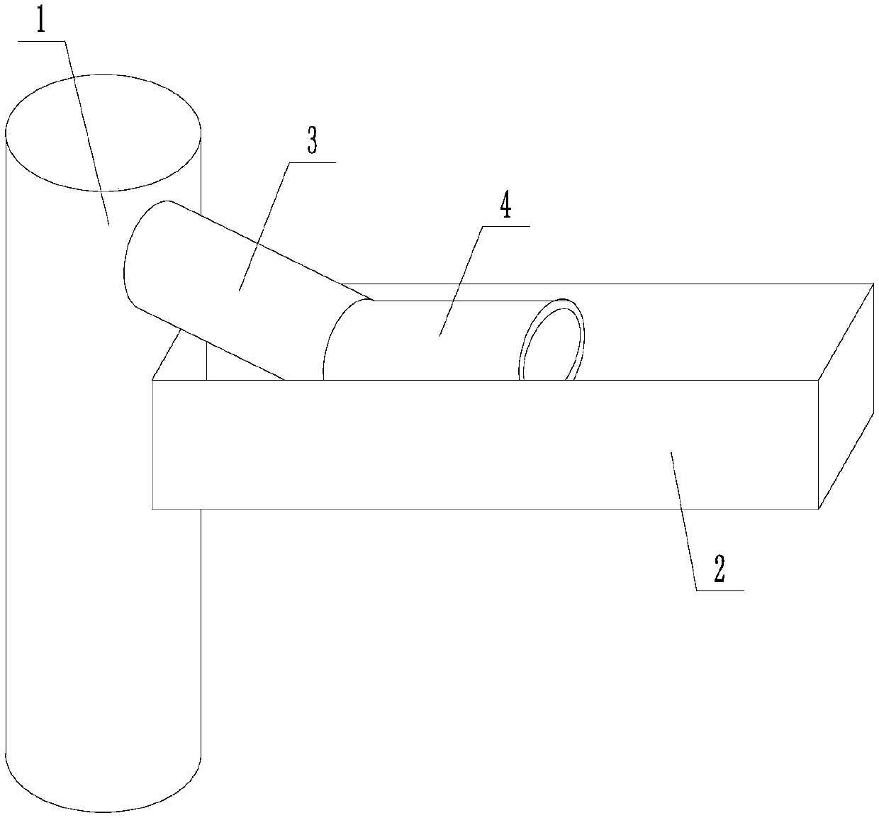
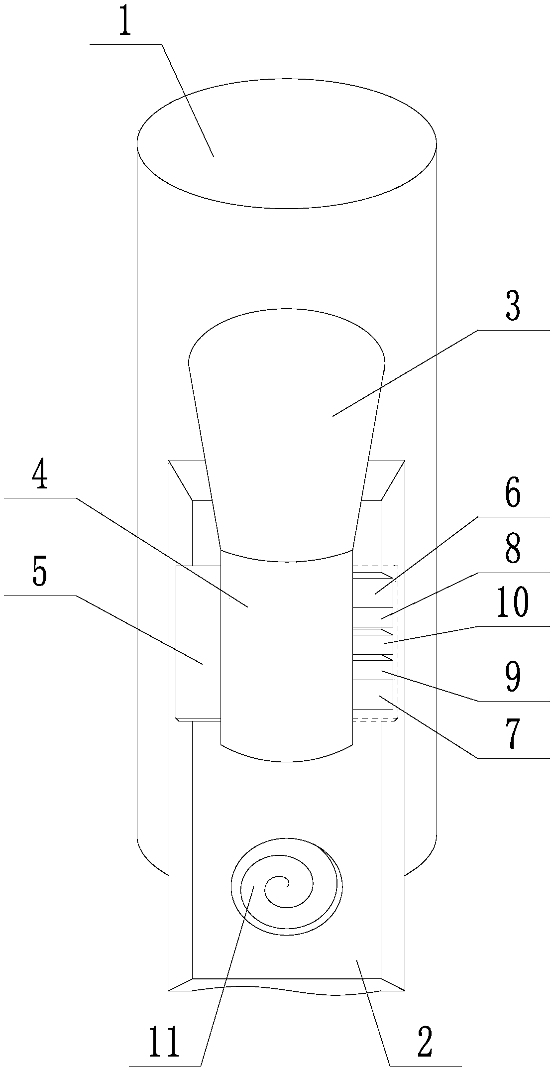
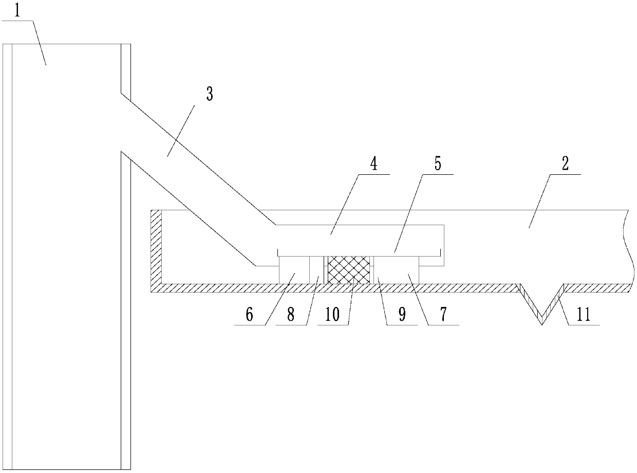
[0028] like Figure 1 to Figure 4 The anti-corrosion structure of the return port of a trumpet tube is shown, in which for the convenience of display, in figure 2 The ceramic mounting plate 5 on the right side has been concealed, including the trumpet tube 1 provided with the return port, the back flow tank 2 connected with the return port of the horn tube 1, the outer surface of the back flow tank 2 is connected with the horn tube 1 No contact, the height of the reflux tank 2 is lower than the height of the return port of the trumpet tube 1, and the horn tube 1 is fixedly connected to the inclined conduit 3 communicated with the return port, and the inclined conduit 3 is directed towards the direction where the reflux tank 2 is located. Downwardly inclined, the end of the inclined conduit 3 away from the trumpet tube 1 is fixedly connected to the parallel conduit 4, the parallel conduit 4 is located in the reflux tank 2, and the axis of the parallel conduit 4 is parallel to ...

Embodiment 2

[0030] like Figure 1 to Figure 6 The anti-corrosion structure of the return port of a trumpet pipe is shown. On the basis of the embodiment, the materials of the trumpet pipe 1, the inclined conduit 3, and the parallel conduit 4 are the same; the return groove 2, the tapered protrusion 11 , The materials of the deflector 12 are the same. The first ceramic spacer 6, the first rubber gasket 8, the bearing frame 10, the second rubber gasket 9, and the second ceramic spacer 7 are all square structures with an arc groove 13 on the upper part. The radius of the arc groove 13 is equal to the outer diameter of the parallel conduit 4 . The opposite side surfaces of the carrying frame 10 along the length direction of the backflow tank 2 are grids composed of mutually perpendicular wooden strips. The ceramic mounting plate 5 extends out of the second ceramic pad 7, and the distance between the outer end of the ceramic mounting plate 5 and the second ceramic pad 7 is 20 cm. A number o...


PUM


Abstract

The invention discloses an anticorrosion structure of a return outlet of the trumpet tube. A parallel guide tube, an inclined guide tube and the trumpet tube form an electric communication whole body,the whole body is not in contact with a backflow groove, a channel for electrochemical corrosion between the trumpet tube and the backflow groove is cut off directly, by cooperation of a ceramic mounting plate, a first ceramic cushion block, a first rubber sealing pad, a carrying frame, a second rubber sealing pad and a second ceramic cushion block, mounting carrying, sealing protection and automatic reinforcing are carried out, the problem that a position where a trumpet tube is connected with a backflow groove in the prior art is corroded quite easily is solved, and purposes of relieving the corrosion rate of the position where the trumpet tube is connected with the backflow groove and reducing the maintaining and changing frequency are achieved.

Description

technical field [0001] The invention relates to the field of anti-corrosion, in particular to an anti-corrosion structure for a return port of a trumpet tube. Background technique [0002] In the field of petroleum exploration, the drilling and completion process is the most important part of the entire development process. The quality of drilling and completion directly determines the skin factor, well quality, and design deviation of a single well, which indirectly determines the single well. well recovery. The wellhead and the drill floor need to be set up during the drilling and completion process. For land oil fields, the wellhead is located on the ground, and the drill floor is at the bottom of the derrick above the wellhead; for offshore oil fields, the wellhead is located on the lower platform, and the drill floor is located on the upper platform. Therefore, no matter whether it is drilling and completion on land or offshore, it is necessary to connect the wellhead ...

Claims


Application Information

Patent Timeline
Patent Type & Authority Applications(China)
IPC IPC(8): E21B33/03F16L58/00
CPCE21B33/03F16L58/00
Inventor 李艳芬
Owner MIANYANG FEIYUAN TECH CO LTD
Why Eureka
Try Eureka