Anti-blocking and anti-corrosion structure for junction of horn pipe and backflow groove

A trumpet tube and anti-blocking technology, which is applied in wellbore/well components, earthwork drilling, flushing wellbore, etc., can solve the problems of easy corrosion at the connection between the horn tube and the return flow tank, and reduce the frequency of maintenance and replacement

Active Publication Date: 2019-01-01
MIANYANG FEIYUAN TECH CO LTD
View PDF6 Cites 0 Cited by
  • Summary
  • Abstract
  • Description
  • Claims
  • Application Information

AI Technical Summary

Problems solved by technology

[0003] The object of the present invention is to provide an anti-blocking and anti-corrosion structure for the connection between the horn tube and the reflux tank, so as to solve the problem that corrosion is easily occurred at the joint between the horn tube and the reflux tank in the prior art, and to realize slowing down of the horn tube. Corrosion rate at the connection with the reflux tank, the purpose of reducing the frequency of maintenance and replacement

Method used


Image

  • Anti-blocking and anti-corrosion structure for junction of horn pipe and backflow groove
  • Anti-blocking and anti-corrosion structure for junction of horn pipe and backflow groove
  • Anti-blocking and anti-corrosion structure for junction of horn pipe and backflow groove

Examples


Embodiment 1

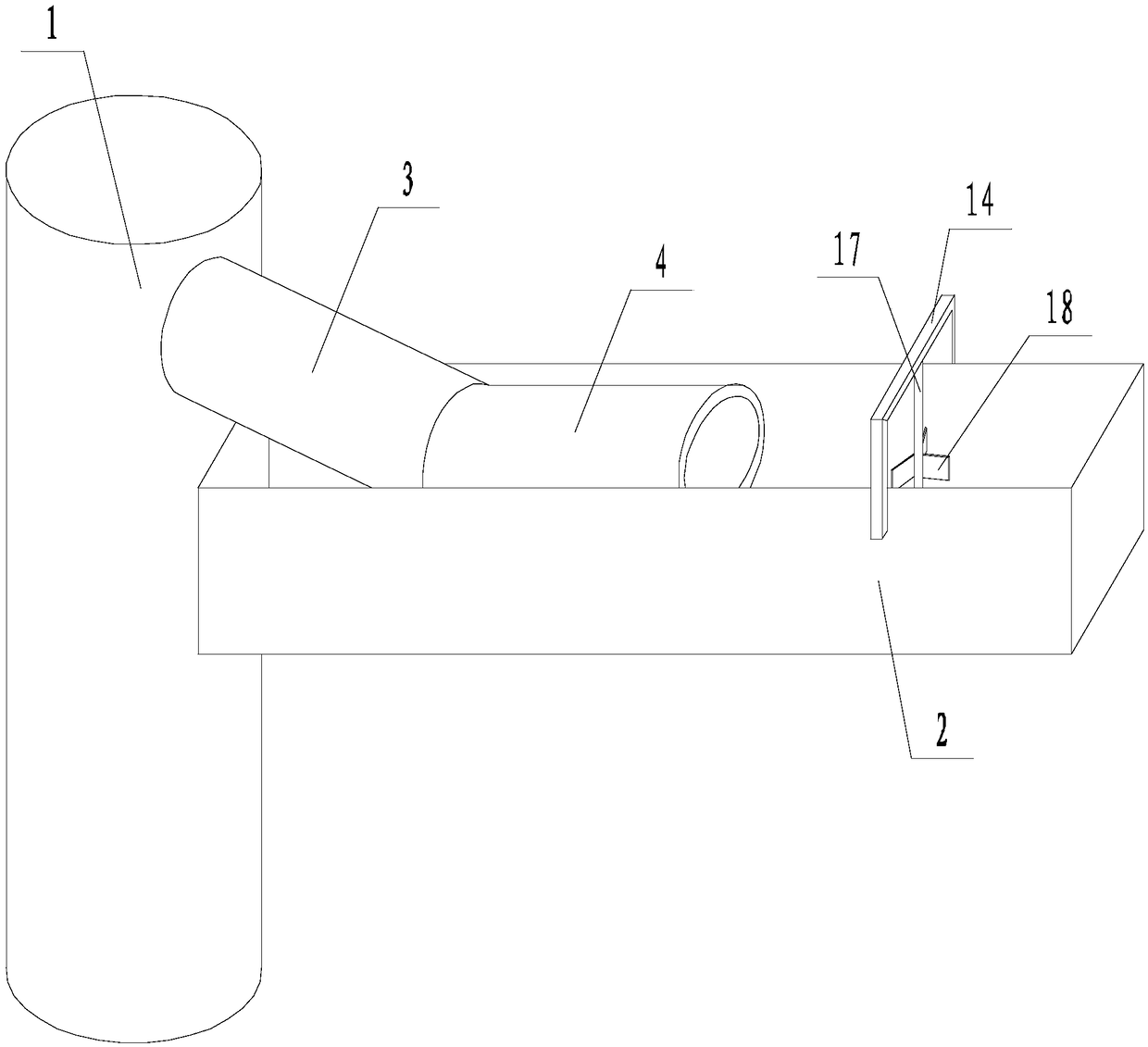
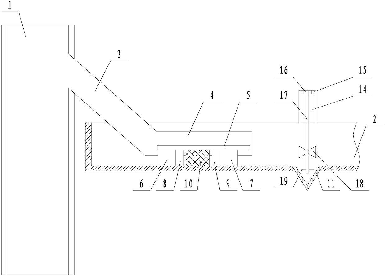
[0028] like Figure 1 to Figure 7 The anti-blocking and anti-corrosion structure used for the connection between the trumpet tube and the reflux tank is shown. For the convenience of display, in figure 2 The ceramic mounting plate 5 on the right side and the gantry frame 14 have been hidden as a whole, including the trumpet pipe 1 provided with the return port, the back flow tank 2 connected to the return port of the trumpet pipe 1, and the back flow tank 2 The outer surface is not in contact with the trumpet tube 1, and the height of the reflux groove 2 is lower than the height of the return port of the trumpet tube 1. The horn tube 1 is fixedly connected with an inclined conduit 3 communicated with the return port, and the inclined conduit 3 faces the return port. The direction of the launder 2 is inclined downward, and the end of the inclined conduit 3 away from the trumpet tube 1 is fixedly connected to the parallel conduit 4. The parallel conduit 4 is located in the refl...

Embodiment 2

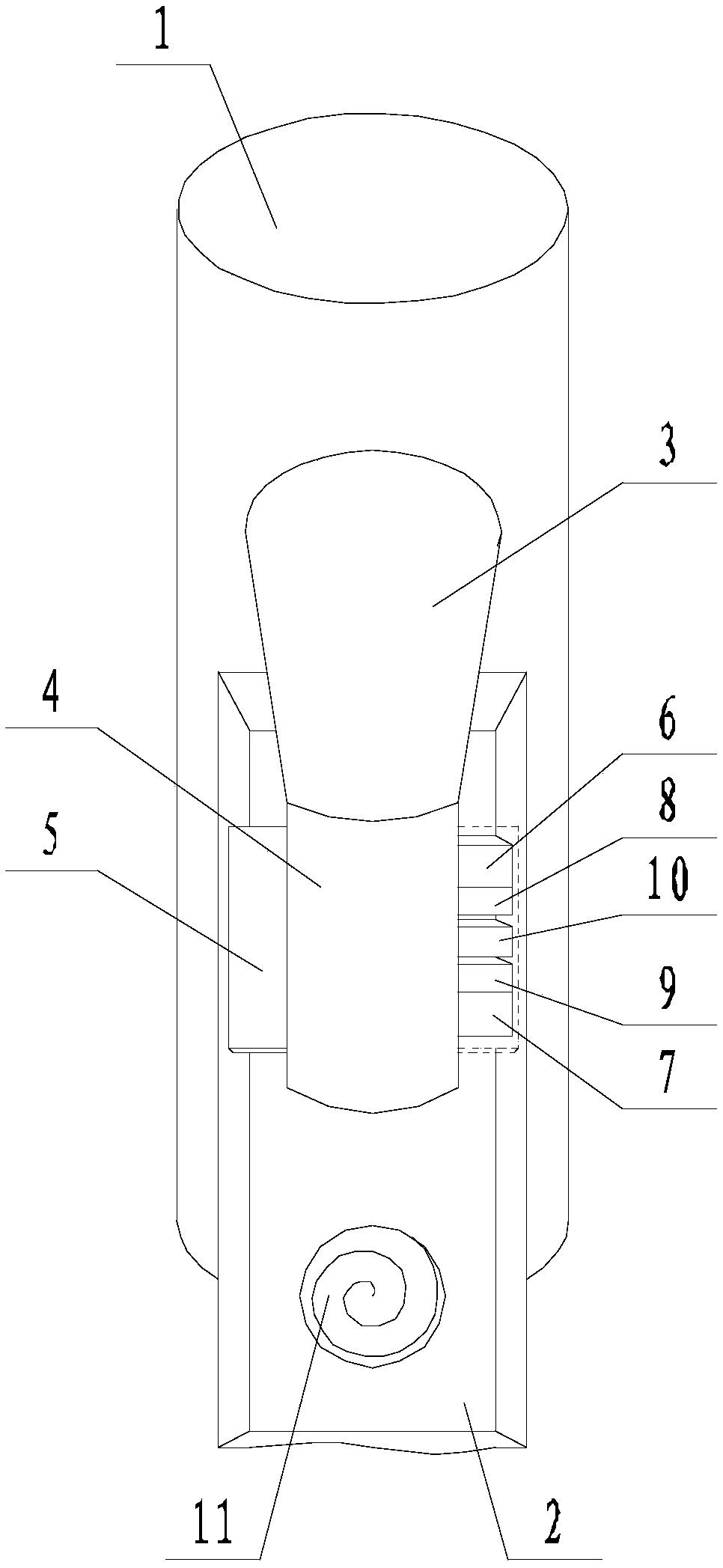
[0030] like Figure 1 to Figure 7 The shown anti-blocking and anti-corrosion structure for the connection between the horn tube and the reflux tank, on the basis of the embodiment, the materials of the horn tube 1, the inclined conduit 3, and the parallel conduit 4 are the same; the reflux tank 2 , the tapered protrusion 11, the deflector 12, the baffle 18, and the blade 19 are made of the same material. A number of blind holes 20 are evenly distributed on the surface of the second ceramic pad 7 facing the direction of the conical protrusion 11 , and the opening diameter of the blind holes 20 is 2.5 cm. The first ceramic spacer 6, the first rubber gasket 8, the bearing frame 10, the second rubber gasket 9, and the second ceramic spacer 7 are all square structures with an arc groove 13 on the upper part. The radius of the arc groove 13 is equal to the outer diameter of the parallel conduit 4; the opposite sides of the bearing frame 10 along the length direction of the backflow...


PUM


Abstract

The invention discloses an anti-blocking and anti-corrosion structure for the junction of a horn pipe and a backflow groove. The electrically communicating whole is composed of a parallel guiding pipe, an inclined guiding pipe and the horn pipe and does not make contact with the backflow groove, and an electrochemical corrosion passage between the horn pipe and the backflow groove is directly cutoff; a ceramic mounting plate, a first ceramic cushion block, a first rubber sealing pad, a bearing frame, a second rubber sealing pad and a second ceramic cushion block are matched to conduct mounting bearing, sealed protection and automatic reinforcing, thus the problem that in the prior art, the junction of the horn pipe and the backflow groove are extremely prone to corrosion is solved, and the purposes of decreasing the corrosion rate of the junction of the horn pipe and the backflow groove and decreasing the maintenance and replacement frequency are achieved; and meanwhile, the anti-blocking and anti-corrosion structure is high in stability, can be self-sealed, and can significantly lower the blocking risk of the backflow groove.

Description

technical field [0001] The invention relates to the field of anti-corrosion, in particular to an anti-blocking and anti-corrosion structure used at the junction of a trumpet tube and a reflux tank. Background technique [0002] In the field of petroleum exploration, the drilling and completion process is the most important part of the entire development process. The quality of drilling and completion directly determines the skin factor, well quality, and design deviation of a single well, which indirectly determines the single well. well recovery. The wellhead and the drill floor need to be set up during the drilling and completion process. For land oil fields, the wellhead is located on the ground, and the drill floor is at the bottom of the derrick above the wellhead; for offshore oil fields, the wellhead is located on the lower platform, and the drill floor is located on the upper platform. Therefore, no matter whether it is drilling and completion on land or offshore, i...

Claims


Application Information

Patent Timeline
Patent Type & Authority Applications(China)
IPC IPC(8): E21B41/02E21B21/06
CPCE21B21/06E21B41/02
Inventor 李艳芬
Owner MIANYANG FEIYUAN TECH CO LTD
Why Eureka
Try Eureka