
Packing shaft seal structure for high pressure reciprocating pump

A technology for reciprocating pumps and shaft seals, which is applied in the packing shaft seal structure and the sealing field of high-pressure or ultra-high-pressure valve stems. It can solve problems such as limited effect, unreasonable radial pressure distribution of packing rings, and high manufacturing precision requirements.

Active Publication Date: 2015-12-09
CHINA CHENGDA ENG
View PDF6 Cites 0 Cited by
  • Summary
  • Abstract
  • Description
  • Claims
  • Application Information

AI Technical Summary

Problems solved by technology

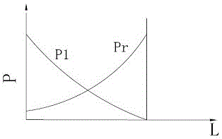
[0005] Defect 1, the radial pressure distribution of the packing ring is very unreasonable: the axial force F acting on the packing ring by tightening the packing gland nut is divided by the annular area of ​​the packing cavity, which is the axial pressure Px acting on the packing ring (bar), while the radial pressure Pr=k.Px of the packing ring acting on the plunger, the lateral pressure coefficient k of the packing is less than 1, and its value is related to the characteristics of the packing ring material and the medium pressure
[0006] Defect 2: In order to reduce the leakage of the shaft seal, the packing gland nut is often over-tightened, thus accelerating the wear of the outer packing ring and plunger and shortening its working life
[0007] Defect three, the seal of the reciprocating pump plunger is to withstand the discharge pressure of the pump. When the discharge pressure of the reciprocating pump is very high, such as the high-pressure ammonia pump and high-pressure methylammonium pump in the urea plant, the discharge pressure of the pump is 200~250bar; BDO The BYD feed pump in the device, the discharge pressure of the pump is about 310bar
[0010] The prior art of sealing the plunger of the high-pressure reciprocating pump uses a series double stuffing box. Although it helps to compress the packing in the inner section, the two-section stuffing box still has the defect that the two pressure distributions in the traditional packing seal are just opposite, and because of The high-pressure reciprocating pump requires a large number of packing rings, and the packing ring is pressurized from the outside, and the pressure has been attenuated when it is transmitted to the inner packing ring. Therefore, the double stuffing box structure is unreasonable for improving the radial pressure distribution of the traditional packing ring on the plunger. The effect of the defect is limited, and because the axial dimension of the stuffing box is too long, the manufacturing precision is required to be high, and the manufacturing cost is increased
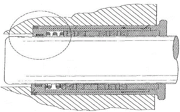
[0011] like image 3 As shown, the inner spring disclosed in US Patent No. 8,100,40 is to install an inner spring inside the stuffing chamber, in order to overcome the big defect of the traditional stuffing seal structure on the principle of pressurizing the stuffing ring from the outside, and help to compress the stuffing inside, but When the packing ring wears and makes its size smaller, the axial pressure of the inner spring will decrease accordingly, and the structure cannot be adjusted.
Moreover, the material of the spring immersed in the pumping medium should be resistant to the corrosion of the pumping medium, and must have the high strength required by the spring. Spring materials that meet these two requirements are not easy to obtain.
Due to the small number of packing rings, this shaft seal structure is only used in occasions where the pumped medium is not highly corrosive and the working pressure is not high.
[0012] The existing technology also adopts the structure of adding internal springs on the outside and inside of the stuffing cavity. The way of adding springs on the outside still has the big defect that the two pressure distributions in the traditional stuffing seal are just opposite.

Method used


Image

  • Packing shaft seal structure for high pressure reciprocating pump
  • Packing shaft seal structure for high pressure reciprocating pump
  • Packing shaft seal structure for high pressure reciprocating pump

Examples


Embodiment Construction

[0032] Below in conjunction with accompanying drawing, the present invention is described in detail.

[0033] In order to make the object, technical solution and advantages of the present invention clearer, the present invention will be further described in detail below in conjunction with the accompanying drawings and embodiments. It should be understood that the specific embodiments described here are only used to explain the present invention, not to limit the present invention.

[0034] Such as Figure 4 As shown, the packing shaft seal structure for high-pressure reciprocating pumps includes a shaft seal box 2 fixedly connected to the pump body 1 and a plunger 3 placed in the shaft seal box 2 through the pump body 1. Between the box 2 and the plunger 3 , on the inside and outside of the shaft seal box 2 , there are respectively a pressurized piston type packing shaft seal assembly and a reverse pull type packing shaft seal assembly.

[0035]Wherein, the pressurized pist...


PUM


Abstract

The invention discloses a packing shaft seal structure for a high-pressure reciprocation pump. The packing shaft seal structure for the high-pressure reciprocation pump comprises a shaft seal box connected on a pump body and a plunger arranged in the shaft seal box, a pressurizing piston type packing shaft seal assembly is arranged between the shaft seal box and the plunger, and a counter pull type packing shaft seal assembly is arranged inside and outside the shaft seal box. According to the packing shaft seal structure for the high-pressure reciprocation pump, the two kinds of internal pressure type packing shaft seal assemblies are used in a series connection mode, the distribution of the sealing radial force on the plunger by a packing ring is made to be identical the distribution of pressure of pumped media, the sealing radial force on the plunger by the packing ring is adjusted automatically along with the change of the pressure of the media inside the shaft seal box, dropped pressure occurring caused by abrasion of the packing ring can be compensated automatically, the defect that the sealing radial force on the plunger by the packing ring is just opposite to the pressure of the media in distribution in an existing external pressure type packing shaft seal structure is overcome, excessively fast abrasion of the outside packing ring and the plunger is avoided, and the reliability of the shaft seal is improved. The packing shaft seal structure is especially suitable for shaft seals of high-pressure or ultrahigh-pressure reciprocation pumps or the sealing of high-pressure or ultrahigh-pressure valves and valve rods.

Description

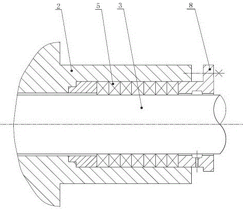
technical field [0001] The invention relates to the technical field of shaft seals of high-pressure reciprocating pumps, in particular to a packing shaft seal structure for high-pressure or ultra-high-pressure reciprocating pumps of BDO and urea devices, and is also suitable for sealing high-pressure or ultra-high-pressure valve stems. Background technique [0002] Packing seal is a kind of traditional contact seal, which is widely used in various industrial sectors because of its simple structure, convenient replacement and low cost, especially for the sealing of reciprocating pump plunger, which is a form commonly used at home and abroad. For traditional packing seal structure see attached figure 1 , mainly including the shaft seal box 2, the plunger 3, the packing ring 5 of the pressurized section, and the packing gland 8. Since the packing is an elastoplastic body, when the packing ring is subjected to axial pressure by the packing gland, the packing deformation produces...

Claims


Application Information

Patent Timeline
Patent Type & Authority Patents(China)
IPC IPC(8): F16J15/16F16J15/56F16K41/06F04B53/00
Inventor 魏宗胜漆明贵张健
Owner CHINA CHENGDA ENG
Learn More