Method of manufacturing liquid ejecting head

a technology of ejecting head and liquid, which is applied in the direction of manufacturing tools, applications, drawing profiling tools, etc., can solve the problems of affecting the filter, omission of dot, and defective discharg

Inactive Publication Date: 2011-01-04
SEIKO EPSON CORP
View PDF12 Cites 6 Cited by
  • Summary
  • Abstract
  • Description
  • Claims
  • Application Information

AI Technical Summary

Benefits of technology

[0008]An advantage of some aspects of the invention is that it provides a method of manufacturing a liquid ejecting head that prevents leakage of liquid even with an easy-to-handle filter that covers a plurality of flow passages.
[0010]According to the above aspect, the outer portion fixes and integrates the first supply member, the filters and the second supply member. This eliminates the necessity for regions for separately thermally welding the filters to the first supply member and to the second supply member. Thus, it is possible to reduce the interval between the adjacent supply elements by increasing the effective area of each filter and, therefore, the size of the head is reduced. In addition, it is not necessary to reduce the area of the filter for reducing the size of the head. This prevents an increase in dynamic pressure and, therefore, it is not necessary to increase a driving voltage at which a pressure generating device, such as a piezoelectric element or a heater element, is driven. Furthermore, the outer portion reliably is able to prevent occurrence of a gap between the supply element and the supply member, and the partition portion formed by separating the connecting portion is able to completely partition the filter element of each liquid supply portion. Thus, leakage of liquid through a gap may be reliably prevented, and leakage between the adjacent liquid supply passages may be prevented. In addition, it is not necessary to separately fix the filters respectively to the first supply member and to the second supply member. Thus, it is possible to reduce manufacturing cost.
[0011]Here, a partition portion molding portion, which is a cavity for molding a partition portion that partitions the filter element portions, may be formed in a region, corresponding to the connecting portion of the connected filter, of a die into which the molten resin is charged, and the connecting portion may be suspended within the partition portion molding portion when the connected filter is placed in the die. With this configuration, the connecting portion is further reliably separated by the pressure of molten resin and, therefore, it is possible to further completely partition the filters by the partition portion.
[0013]In addition, tear-off lines that facilitates separation by pressure of the molten resin may be formed in the connecting portion of the connected filter. With this configuration, it is possible to mold the partition portion by further reliably separating the connecting portion at portions of the tear-off lines by pressure of molten resin. Thus, it is possible to further reliably partition the filters by the partition portion.
[0016]In addition, each filter may have an outer shape corresponding to a filter holding portion of a peripheral portion of a corresponding one of the liquid supply passages, and the outer portion may extend continuously to an outer peripheral end surfaces of the filter in a gap between the first supply member and the second supply member. With this configuration, the outer peripheral end surfaces of each filter is covered with the outer portion while the area of the peripheral portion of each filter is minimized, and occurrence of a gap between the first supply member and the second supply member is reliably prevented. Thus, it is possible to further reliably prevent leakage of liquid through a gap.

Problems solved by technology

In the above ink jet recording head, when bubbles that are present in ink contained in the ink cartridge or bubbles trapped into ink when the ink cartridge is attached or detached are supplied to the head element, the bubbles problematically cause defective discharge, such as dot omission.
When small filters are separately prepared and attached to respective flow passages, it is difficult to handle the filters.
However, in this case, there is a possibility that liquid that flows through different flow passages may leak through the filter.

Method used


Image

  • Method of manufacturing liquid ejecting head
  • Method of manufacturing liquid ejecting head
  • Method of manufacturing liquid ejecting head

Examples


first embodiment

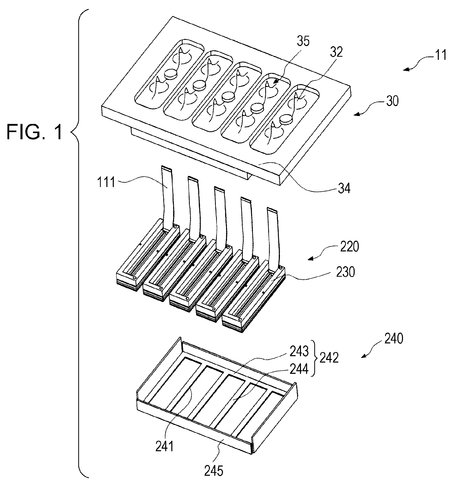
[0031]FIG. 1 is an exploded perspective view of an ink jet recording head, which is an example of a liquid ejecting head manufactured by a method of manufacturing a liquid ejecting head, according to a first embodiment of the invention.

[0032]First, the configuration of the recording head 11 will be described. As shown in FIG. 1, the recording head 11 includes a supply member 30 such as a cartridge case, a head element 220, and a cover head 240. The ink cartridges 13, which are liquid reservoir portions, are fixed to the supply member 30. The head element 220 is fixed to a surface of the supply member 30, which is opposite to a side on which the ink cartridges 13 are fixed. The cover head 240 is provided on a liquid ejecting surface side of the head element 220.

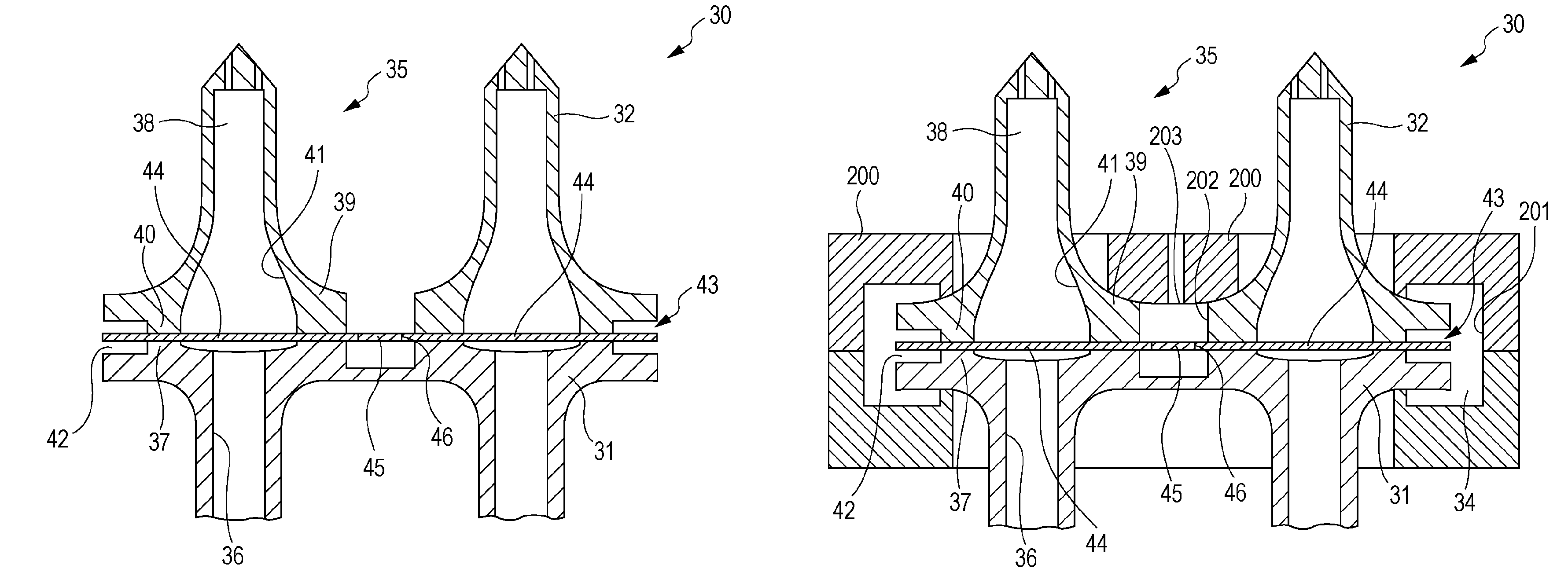
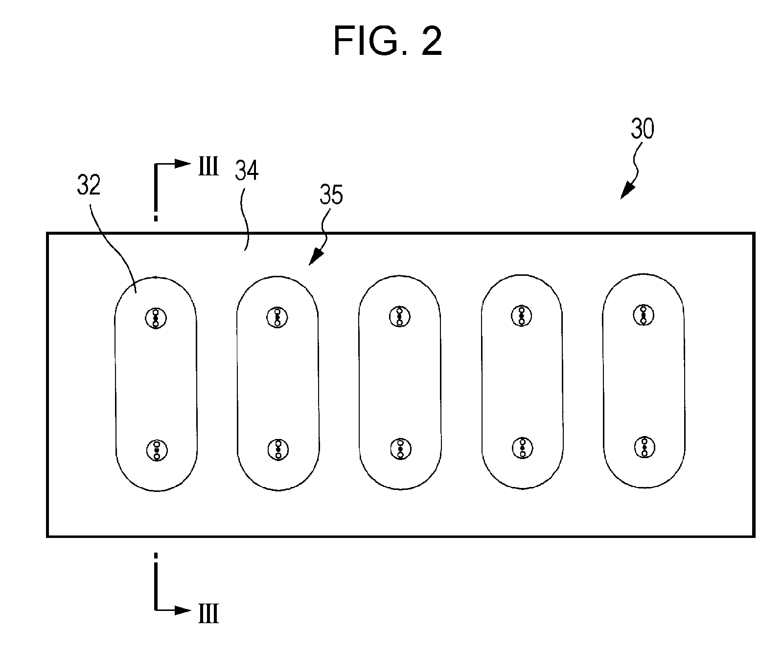
[0033]Here, the supply member 30 will be described in detail. Note that FIG. 2 is a top view of the supply member, FIG. 3 is a cross-sectional view that is taken along the line III-III in FIG. 2, and FIG. 4 is a view that illu...

second embodiment

[0072]FIG. 9A is a plan view that shows the outer shape of connected filter according to a second embodiment. FIG. 9B is a plan view in the process of manufacturing a supply member according to the second embodiment. The supply member 30A of the present embodiment is formed so that filter element portions 44A of the connected filter 43A have a size corresponding to a region in which a filter 33A at the peripheral portion of each liquid supply passage 36 is held, and resin enters to contact the outer peripheral end surfaces of the filter element portions 44A to form the outer portion 34. Thus, the outer peripheral ends of the filters 33A are reliably sealed by the outer portion 34A, and the supply member element 31, the supply needles 32 and the filters 33A are reliably integrated.

Alternative Embodiment

[0073]The embodiments of the invention are described above; however, the basic configuration of the aspects of the invention is not limited to the above described embodiments.

[0074]For...


PUM

PropertyMeasurementUnit
pressureaaaaaaaaaa
heataaaaaaaaaa
outer shapeaaaaaaaaaa

Abstract

A method of manufacturing a liquid ejecting head and a supply member having a plurality of liquid supply passages is provided. The supply member includes first and second supply members in which liquid supply passages are provided and filters provided between the first supply member and the second supply member. The method includes: preparing a connected filter formed of a plurality of filter element portions corresponding to the plurality of liquid supply passages and a connecting portion that connects the plurality of filter element portions; in a state where the filter element portions of the connected filter are held between the first supply member and the second supply member, charging molten resin from a position corresponding to the connecting portion of the connected filter to separate the connecting portion; and, during the charging, molding.

Description

BACKGROUND[0001]1. Technical Field[0002]The invention relates to a method of manufacturing a liquid ejecting head that ejects liquid and, more particularly, to a method of manufacturing an ink jet recording head that discharges ink as liquid.[0003]2. Related Art[0004]In an ink jet recording head, which is a typical liquid ejecting head, generally, ink is supplied from an ink cartridge, which is a liquid reservoir portion and filled with ink, to a head element through an ink flow passage, which is formed in a supply member, such as an ink supply needle, which is an ink supply element and detachably inserted into the ink cartridge, and a cartridge case in which the ink cartridge is held, and the ink supplied to the head element is discharged from a nozzle by driving a pressure generating device, such as a piezoelectric element, provided for the head element.[0005]In the above ink jet recording head, when bubbles that are present in ink contained in the ink cartridge or bubbles trapped...

Claims


Application Information

Patent Timeline
Patent Type & Authority Patents(United States)
IPC IPC(8): B29C45/14
CPCB29C65/70B41J2/161B29C66/543B41J2/1626B41J2/175B41J2/17563B29C66/5412B41J2/1623B29L2031/14B29L2031/767
Inventor KAMIKURA, HIROYUKI
Owner SEIKO EPSON CORP
Why Eureka
Try Eureka