STED-fluorescent light microscopy with two-photon excitation

a fluorescence light and microscopy technology, applied in the field of sted-fluorescent light microscopy with two-photon excitation, can solve the problems of high technical effort and financial investment, laser pulses emitted by usual pulse lasers do not display a sufficient pulse duration for sted fluorescence, and achieve high spatial resolution

Active Publication Date: 2011-01-04
MAX PLANCK GESELLSCHAFT ZUR FOERDERUNG DER WISSENSCHAFTEN EV
View PDF12 Cites 7 Cited by
  • Summary
  • Abstract
  • Description
  • Claims
  • Application Information

AI Technical Summary

Problems solved by technology

Thus, the efforts for realising an STED fluorescent light microscope or for upgrading a common fluorescent light microscope for STED fluorescent light microscopy are high, because synchronisable pulse lasers for the excitation light and for the de-excitation light are expensive.
In addition, the laser pulses emitted by usual pulse lasers do not display a sufficient pulse duration for STED fluorescence microscopy.
Besides the synchronization requirements, the necessary lengthening and preparation of the pulses via dispersive optical elements like grates and glass fibre arrangements result in high technical efforts and financial investments as well as in a susceptibility to functional failures.
If diode lasers are modified for the emission of single pulses, however, the technical and financial advantages generally provided by them get lost.
In the known forms of STED fluorescent light microscopy it turns out to be difficult to delimit the measurement area along the optical axis, because with a single photon excitation of the fluorescent dye, it is in principle impossible to spatially reduce the excitation to the focal plane or to the focal volume.
Similarly, it is also not possible to delimit the de-excitation to the focal plane.
Although it is possible to reduce the measurement area along the optical axis to the focal plane by using a confocal pinhole in front of the detector, this still means that the fluorescent dye is unnecessarily excited and de-excited outside the focal plane which results in a considerable bleaching of the fluorescent dye particularly by the high intensity de-excitation light, and thus prevents capturing of 3D images with many fluorescent dyes.

Method used


Image

  • STED-fluorescent light microscopy with two-photon excitation
  • STED-fluorescent light microscopy with two-photon excitation

Examples


Embodiment Construction

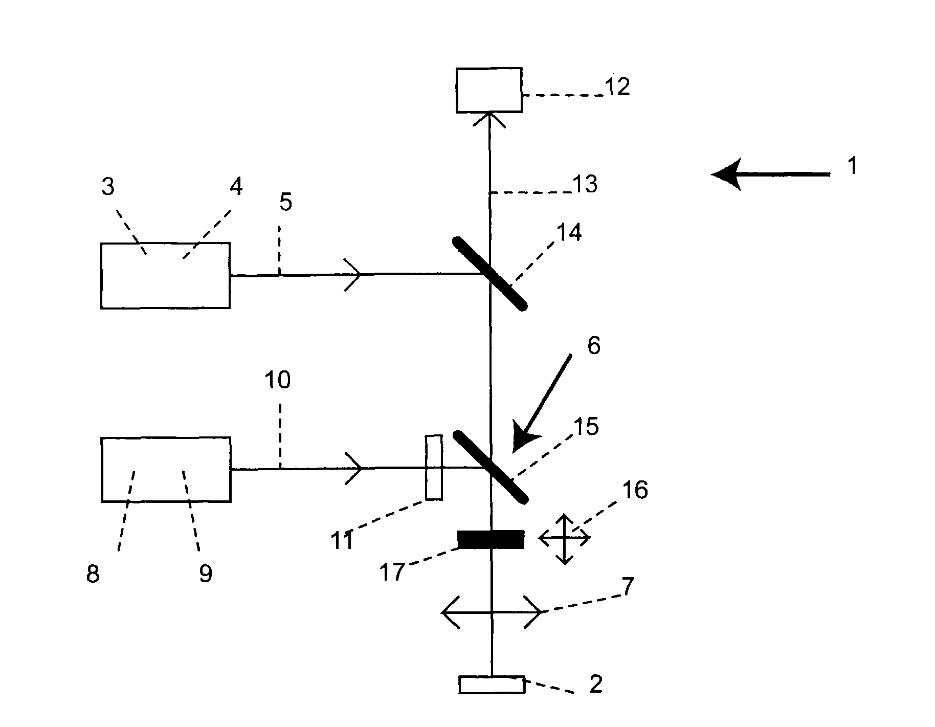
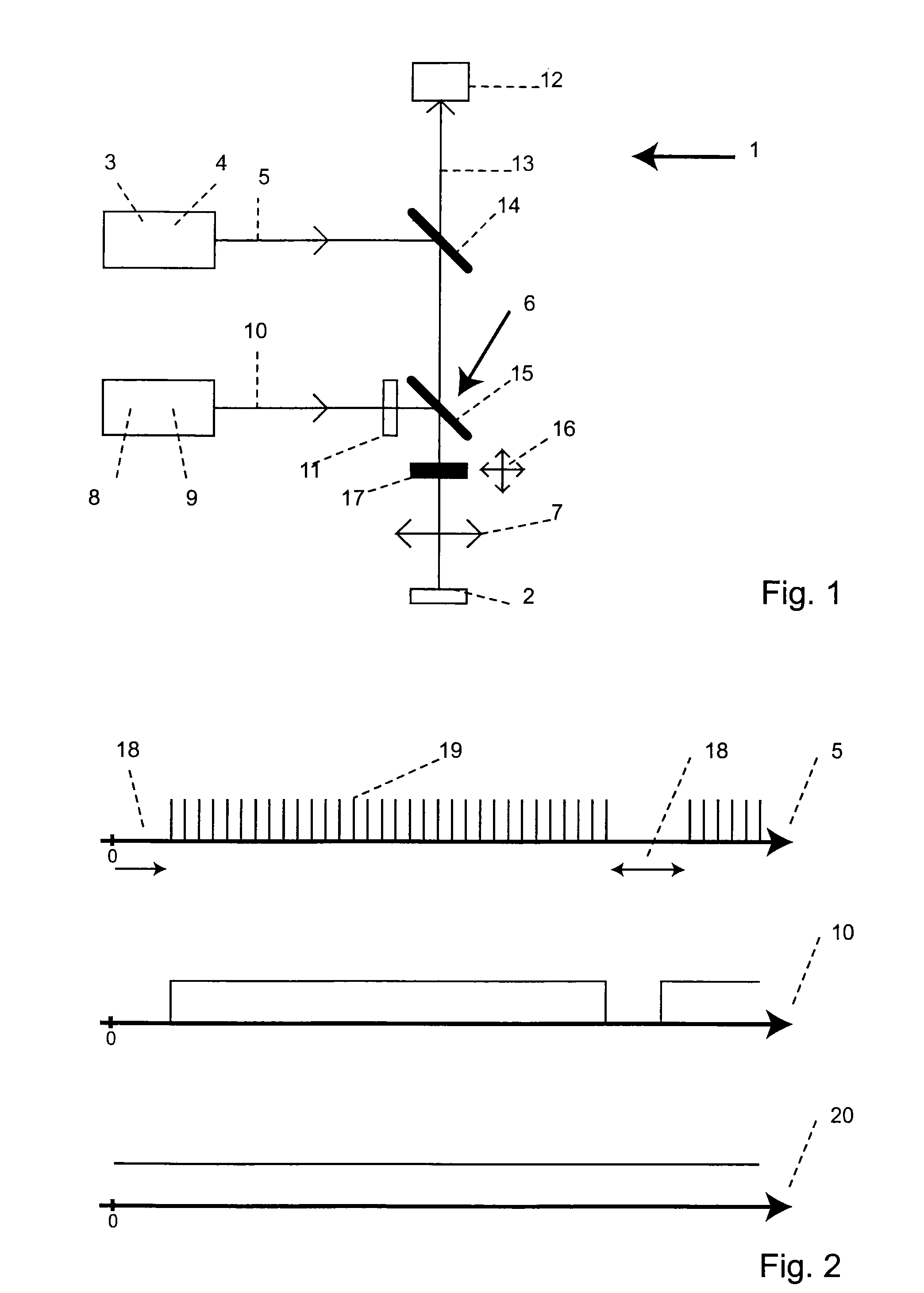
[0021]In the new method, the wavelength of the excitation light is selected in such a way that the excitation light excites the fluorescent dye via a multi photon process. Normally, this will be a two-photon process. Whereas the excitation light for the multi photon excitation is pulsed, which has a positive effect on the fluorescence light yield from the multi photon excitation, the de-excitation light which has a shorter wavelength than the excitation light is continuously directed onto the sample during a plurality of pulses of the excitation light. Because of the excitation of the fluorescent dye with the excitation light via a multi photon process, the focal area in which an effective excitation of the fluorescent dye takes place is considerably spatially limited as compared to an excitation via a single photon process. Particularly, with high aperture objectives, the non-linear excitation by the multi photon process is delimited to a focal depth of typically about ˜1 μm which ...


PUM

PropertyMeasurementUnit
frequencyaaaaaaaaaa
frequencyaaaaaaaaaa
frequencyaaaaaaaaaa

Abstract

A method of high spatial resolution imaging a structure in a sample comprises: marking the structure with molecules of a fluorescent dye; selecting a first wavelength for excitation light which excites the molecules of the fluorescent dye via a multi photon process for spontaneous emission of fluorescent light; focusing pulses of the excitation light into the sample to excite those molecules of the fluorescent dye present in a focal area of the focused excitation light; selecting a second wavelength shorter than the first wavelength for de-excitation light which de-excites excited molecules of the fluorescent dye prior to their spontaneous emission; during a plurality of the pulses of the excitation light, continuously directing the de-excitation light onto the sample to de-excite excited molecules of the fluorescent dye, which are located outside an measurement area which is a fraction of the focal area; and recording the fluorescent light spontaneously emitted by the molecules of the fluorescent dye in the sample.

Description

CROSS REFERENCE TO RELATED APPLICATIONS[0001]The present application is a continuation of International Application PCT / EP2008 / 060694 entitled “STED-Fluorescence Microscopy having two-Photon Excitation”, filed Aug. 14, 2008, and claims priority to co-pending German Patent Application No. DE 10 2007 039 111.2 entitled “STED-Fluoreszenzmikroskopie mit Zweiphotonen-Anregung”, filed Aug. 18, 2007.FIELD OF THE INVENTION[0002]The invention relates to a method of high spatial resolution imaging a structure of interest in a sample, which is marked with molecules of a fluorescent dye, and to a high spatial resolution imaging system comprising a sample in which a structure of interest is marked with molecules of fluorescent dye. More particular, the present invention relates to a method and a system of STED (Stimulated Emission Depletion)-fluorescent light microscopy.BACKGROUND OF THE INVENTION[0003]In STED-fluorescent light microscopy, the diffraction barrier which normally is the resolution...

Claims


Application Information

Patent Timeline
Patent Type & Authority Patents(United States)
IPC IPC(8): G01N21/64
CPCG01N21/636G02B21/0076G01N21/6458
Inventor HELL, STEFAN W.WILLIG, KATRIN
Owner MAX PLANCK GESELLSCHAFT ZUR FOERDERUNG DER WISSENSCHAFTEN EV
Why Eureka
Try Eureka