Electronic assembly having spring-loaded contact bridge with fuse function

a technology of contact bridge and fuse function, which is applied in the direction of printed circuit manufacturing, printed circuit aspects, and addition of non-printed jumper connections, etc., can solve the problems of assembly power dissipation and total destruction of circuit boards, and achieve the effect of avoiding the increase of power dissipation in the assembly

Inactive Publication Date: 2011-01-04
CONTI TEMIC MICROELECTRONIC GMBH
View PDF35 Cites 58 Cited by
  • Summary
  • Abstract
  • Description
  • Claims
  • Application Information

AI Technical Summary

Benefits of technology

[0003]Therefore, the underlying object of the invention is to set forth an electronic assembly of the abovementioned type, which is secured to a high degree by simple means against a possible occurrence of high power dissipation.
[0010]For an especially reliable safety or fuse function, the electronic assembly is advantageously designed in such a manner so that the current supply to the circuit board or to individual components is interrupted in a targeted manner upon the occurrence of an unexpected temperature increase, because thereby the power dissipation can be reduced especially effectively and quickly. In order to ensure this, at least one of the contact bridges is advantageously mounted on a supply conductor strip through which a current feed or supply to the components mounted on the circuit board is carried out.
[0013]The advantages achieved with the invention especially consist in that, through the provision of spring-loaded contact bridges for the production of electrical connections between conductor strips and / or components on the circuit board, upon the occurrence of increased temperatures a melting of the connection location of the contact bridge to the circuit board and associated therewith, due to the springy embodiment, an abrupt interruption of the electrical connection produced by the contact bridge is achievable. Thereby the energy supply to the circuit board in total or to individual components can be interrupted reliably, abruptly and quickly on the assembly, as soon as an unexpected temperature increase occurs. Thereby resultant damages due to increased power dissipation in the assembly are surely avoided.

Problems solved by technology

Depending on the application purpose, with such assemblies an unacceptably high loss power dissipation could arise in the assembly due to faulty components such as switching transistors for example, due to circuit board short circuits, or due to water penetration.
In severe cases, this power dissipation could (lead) to the total destruction of the circuit board.

Method used


Image

  • Electronic assembly having spring-loaded contact bridge with fuse function
  • Electronic assembly having spring-loaded contact bridge with fuse function
  • Electronic assembly having spring-loaded contact bridge with fuse function

Examples


Embodiment Construction

[0019]The same parts are provided with the same reference numbers in all figures.

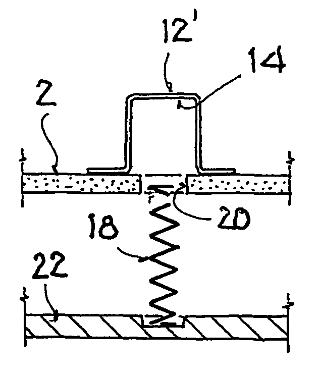
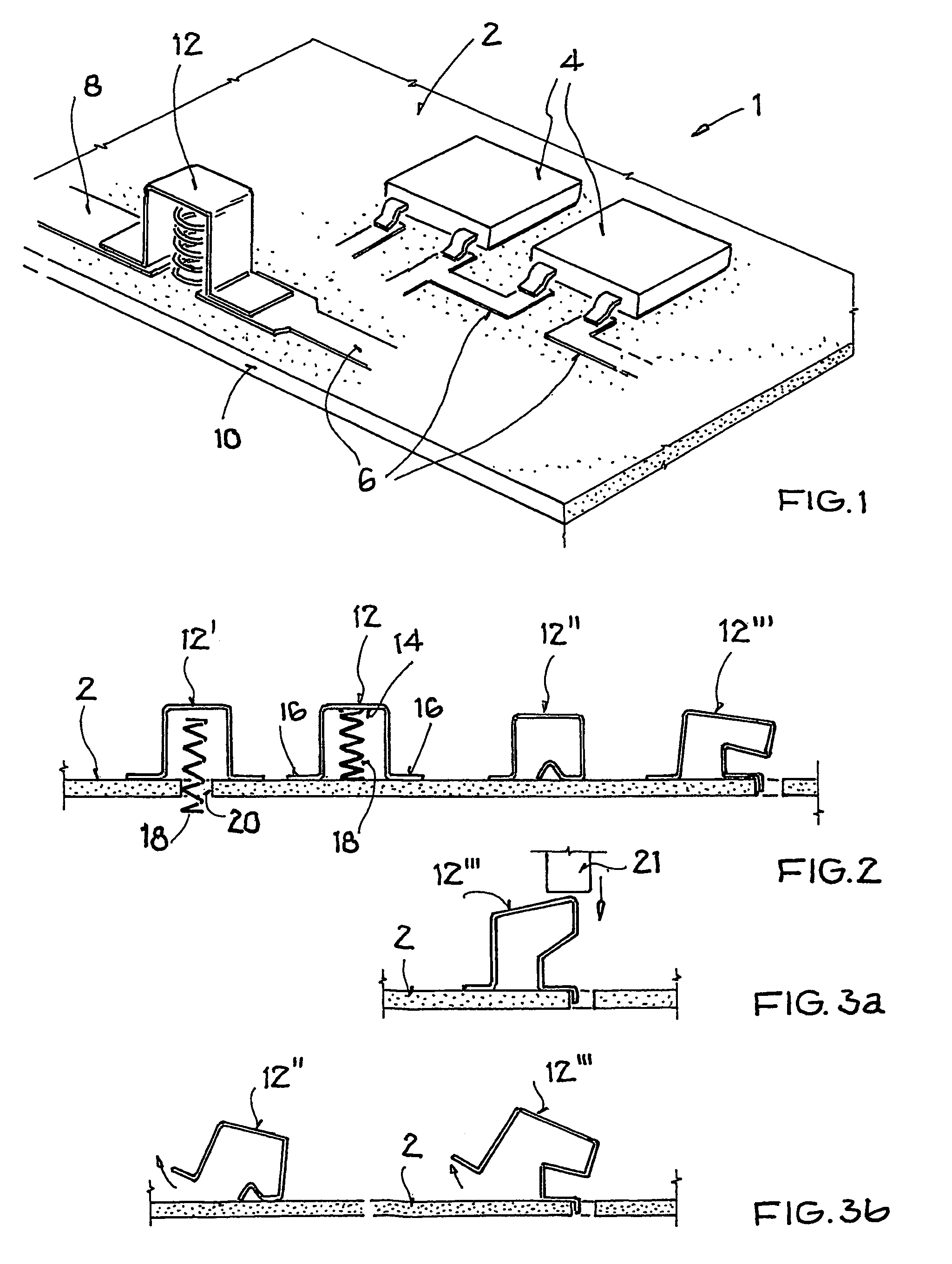
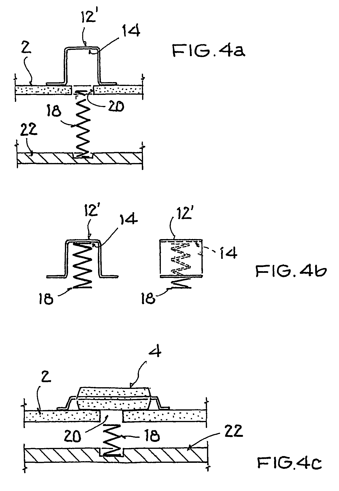
[0020]The electronic assembly 1 schematically illustrated in FIG. 1 is especially provided for use in electronic control devices, such as for example in driving dynamics regulators, ABS regulators, ESP systems or other vehicle control devices of a motor vehicle. It encompasses a circuit board 2 that is equipped with a number of application-specifically embodied SMD components 4 and further electronic and / or electromechanical elements. The SMD components 4 and if applicable the further elements are mounted on the circuit board 2 through use of a suitable solder and are suitably connected with one another via a plurality of conductor strips or paths 6, of which only a few are illustrated in an exemplary manner in the example embodiment.

[0021]In that regard, the circuit board 2 can be embodied as a simple or single circuit board or also as a circuit board with several wiring planes, such as for example a t...


PUM


Abstract

An electronic assembly includes an electronic circuit on a circuit board. The circuit includes a conductor path on the circuit board, and at least one SMD component, electronic component and / or electromechanical component that is mounted on the circuit board and connected to the conductor path. A circuit connection between any two of the conductor paths and / or the components is established via a soldered joint and a spring-loaded contact bridge. In the event of excessive power dissipation, the soldered joint melts or weakens and the contact bridge opens due to the spring force.

Description

FIELD OF THE INVENTION[0001]The invention relates to an electronic assembly with a circuit board that is provided with conductor strips or paths and, for forming an electronic circuit, is equipped with a number of SMD (“Surface Mounted Device”) components and / or further electronic and / or electromechanical elements while using a suitable solder.BACKGROUND INFORMATION[0002]Such electronic assemblies can especially be provided for an application in electronic control devices, for example in driving dynamics regulators, ESP systems or ABS regulators. Depending on the application purpose, with such assemblies an unacceptably high loss power dissipation could arise in the assembly due to faulty components such as switching transistors for example, due to circuit board short circuits, or due to water penetration. In severe cases, this power dissipation could (lead) to the total destruction of the circuit board.SUMMARY OF THE INVENTION[0003]Therefore, the underlying object of the invention ...

Claims


Application Information

Patent Timeline
Patent Type & Authority Patents(United States)
IPC IPC(8): H01H85/36H01H37/76
CPCH01H37/761H05K1/0201H01H2037/762H05K3/222H05K3/3421H05K2201/09072H05K2201/10181H05K2201/10265H05K2203/176
Inventor SCHLENKER, ROBERTONAGEL, MICHAELMARTIN, JUERGEN
Owner CONTI TEMIC MICROELECTRONIC GMBH
Why Eureka
Try Eureka