Maintaining IGP transparency of VPN routes when BGP is used as a PE-CE protocol

a technology of vpn routes and bgp, applied in the field of computer networks, can solve the problems of vpn routes being destroyed, service provider pes not being able to communicate with certain igps, and vpn routes being unable to maintain igp transparency, so as to achieve the effect of maintaining igp transparency of vpn routes

Inactive Publication Date: 2011-01-04
CISCO TECH INC
View PDF8 Cites 21 Cited by
  • Summary
  • Abstract
  • Description
  • Claims
  • Application Information

AI Technical Summary

Benefits of technology

[0030]Advantageously, the novel technique maintains IGP transparency of VPN routes when BGP is used as a PE-CE protocol in a computer network. By configuring the CEs to function as VPN border routers, the novel technique allows for the use of CE-CE BGP advertisements with novel transitive IGP attributes. In particular, the present invention allows for the use of BGP on PE-CE links without losing IGP attributes within a VPN. Also, the present invention does not require PEs to communicate IGP advertisements with CEs (i.e., the PE is not required to be part of the customer's IGP cloud), and does not require any additional configuration of the PEs. Further, the dynamic nature of the novel technique alleviates the need for cumbersome manual configuration.

Problems solved by technology

Some service provider PEs may not be able to communicate with certain IGPs, e.g., proprietary IGPs, such as the Enhanced Interior Gateway Routing Protocol (EIGRP) of Cisco Systems, Inc.
By using BGP as the PE-CE protocol, though, the transparency described above is destroyed.
The VPN routes that are actually internal to the second CE's IGP domain (i.e., and the first CE's IGP domain) are therefore improperly installed as external routes.
In addition to improperly installing internal VPN routes as external routes, any IGP attributes originally sent by the first CE to the first PE through the BGP advertisement will have been lost in the BGP transitions.
Currently, no transitive attributes are available in BGP advertisements that would convey IGP attributes of a first customer network to another customer network.

Method used


Image

  • Maintaining IGP transparency of VPN routes when BGP is used as a PE-CE protocol
  • Maintaining IGP transparency of VPN routes when BGP is used as a PE-CE protocol
  • Maintaining IGP transparency of VPN routes when BGP is used as a PE-CE protocol

Examples


Embodiment Construction

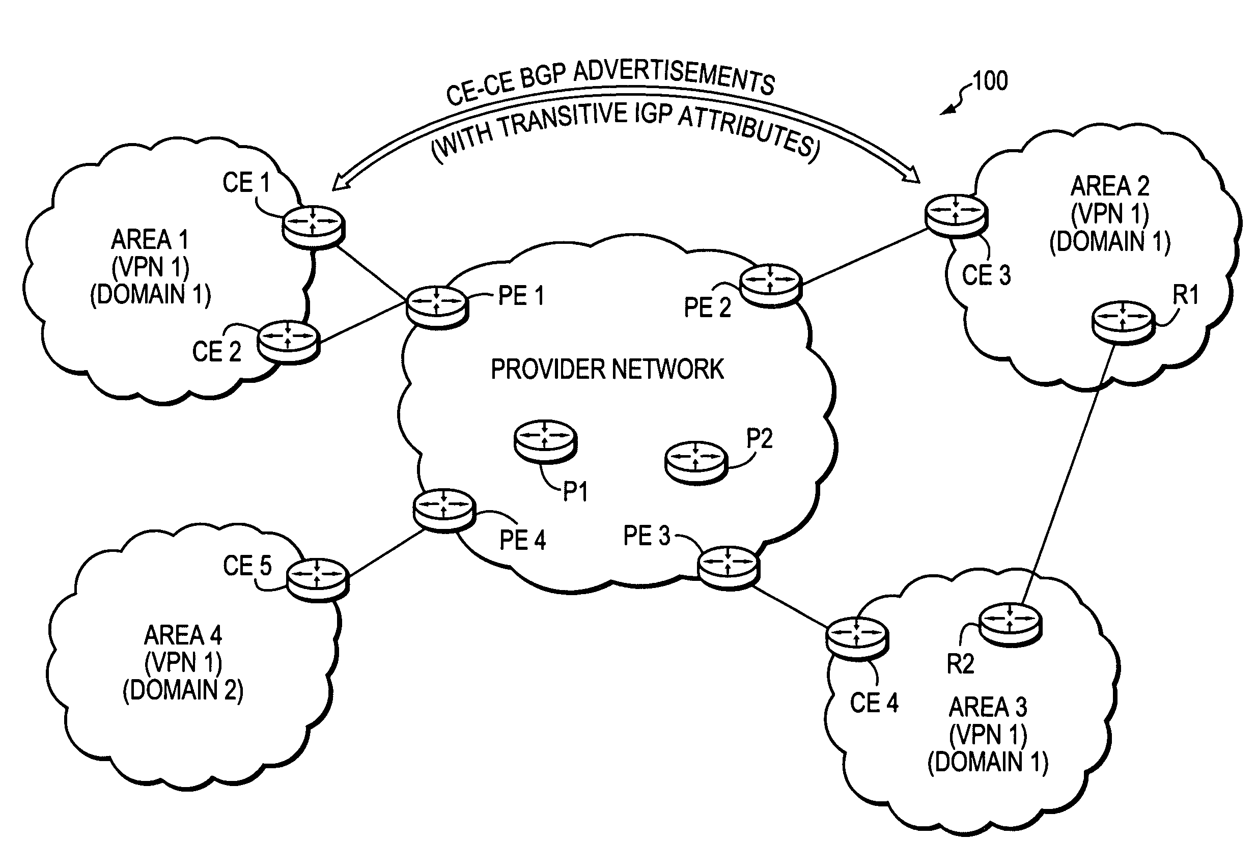
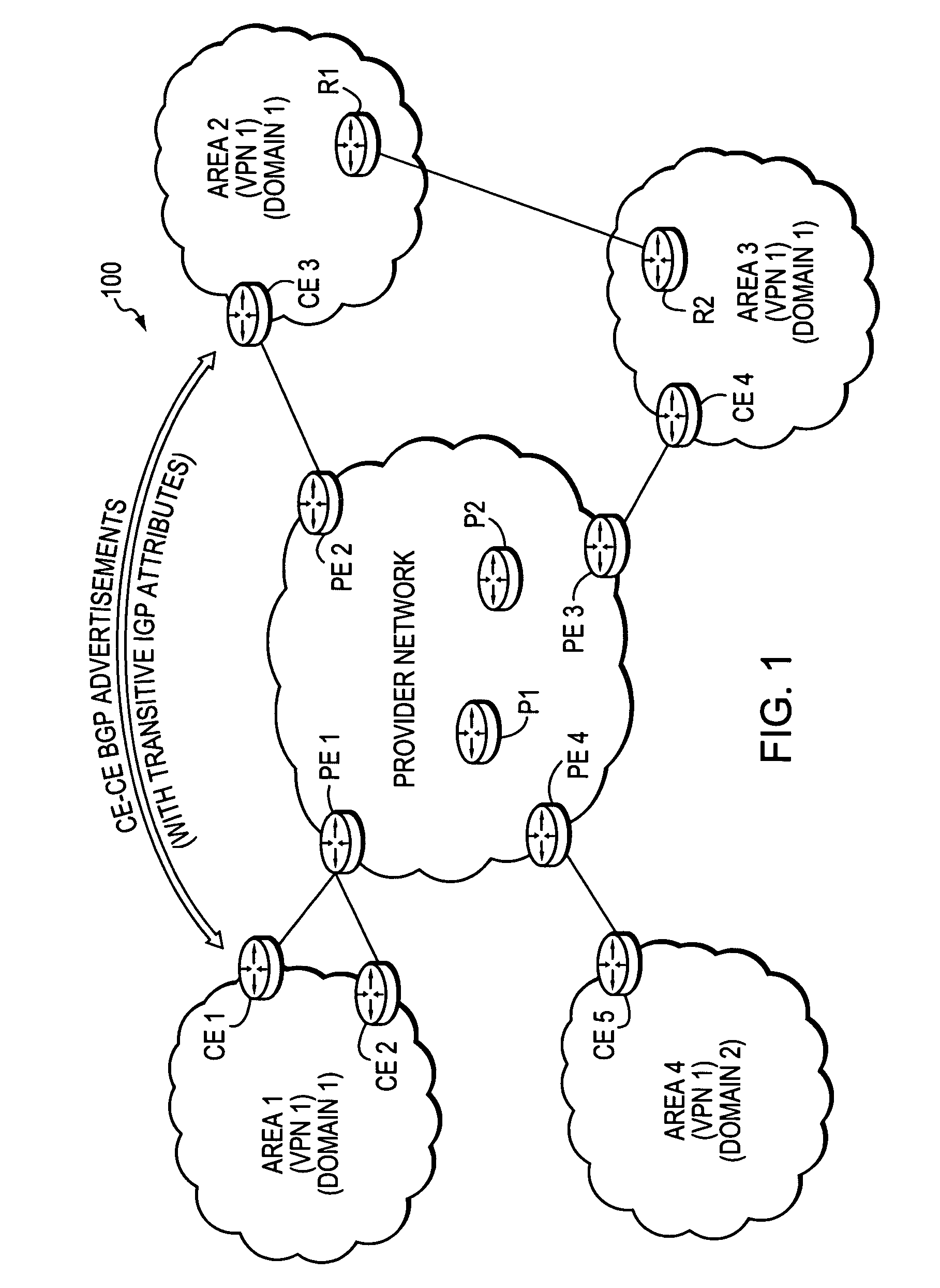
[0037]FIG. 1 is a schematic block diagram of an exemplary computer network 100 comprising a provider network, (e.g., a service provider network) interconnected to two or more customer networks, e.g., Areas 1-4. Although the provider and customer networks are described illustratively herein as autonomous systems, those skilled in the art will appreciate that they may be configured as one or more routing domains or other networks or subnetworks. The provider network comprises one or more network nodes, including a set of communicating border nodes or routers (illustratively, provider edge devices, or “PEs”) PE1-PE4, through which client communications, such as data packet traffic, can pass into and out of the provider network. The provider network may also have zero or more intra-network nodes or routers (e.g., provider devices, or “Ps”), such as to form a “core” within the provider network (e.g., P1 and P2).

[0038]The customer networks also comprise one or more network nodes, includin...


PUM


Abstract

A technique maintains Interior Gateway Protocol (IGP) transparency of Virtual Private Network (VPN) routes when Border Gateway Protocol (BGP) is used as a Provider Edge Device (PE) to Customer Edge Device (CE) protocol in a computer network. According to the novel technique, a first CE generates a BGP advertisement to advertise one or more VPN routes of its customer network, the BGP advertisement having one or more transitive IGP attributes for the advertised routes. The first CE sends the BGP advertisement to a first PE, which then propagates the BGP advertisement among devices of a provider network maintaining the transitive IGP attributes. A second PE sends the BGP advertisement to a second CE, along with the transitive IGP attributes. Upon receiving the BGP advertisement, the second CE converts the BGP advertisement and transitive IGP attributes into corresponding IGP advertisements. The second CE may then propagate the IGP advertisements into its customer network as either internal VPN routes or as external routes accordingly.

Description

BACKGROUND OF THE INVENTION[0001]1. Field of the Invention[0002]The present invention relates to computer networks and more particularly to maintaining Interior Gateway Protocol (IGP) transparency of Virtual Private Network (VPN) routes when Border Gateway Protocol (BGP) is used as a Provider Edge Device (PE) to Customer Edge Device (CE) protocol in a computer network.[0003]2. Background Information[0004]A computer network is a geographically distributed collection of interconnected subnetworks, such as local area networks (LAN), that transport data between network nodes. As used herein, a network node is any device adapted to send and / or receive data in the computer network. Thus, in the context of this disclosure, the terms “node” and “device” may be used interchangeably. The network topology is defined by an arrangement of network nodes that communicate with one another, typically through one or more intermediate network nodes, such as routers and switches. In addition to intra-n...

Claims


Application Information

Patent Timeline
Patent Type & Authority Patents(United States)
IPC IPC(8): G06F15/173
CPCH04L12/66H04L45/02H04L45/04H04L63/0272H04L45/033
Inventor MIRTORABI, SINAPSENAK, PETERSHAIKH, MUKHTIARROSEN, ERIC C.
Owner CISCO TECH INC
Why Eureka
Try Eureka