Transfer tool

a transfer tool and type technology, applied in the field of refilling type transfer tools, can solve the problems of troublesome positioning labor hours, deterioration of transfer performance, and difficulty in assembling, so as to improve the use feeling maintain the strength of the transfer tool, and secure the effect of strength and engagement holding

Active Publication Date: 2011-01-11
KOKUYO S&T CO LTD
View PDF17 Cites 3 Cited by
  • Summary
  • Abstract
  • Description
  • Claims
  • Application Information

AI Technical Summary

Benefits of technology

[0006]Accordingly, the present invention is made by taking the problem mentioned above into consideration, and an object of the present invention is to provide a transfer tool which can preferably maintain a shape while improving a strength at a time of using, and has an improved usability.
[0009]In accordance with the structure mentioned above, since the holding portion securely holds the first case and the second case in the predetermined region, that is, in one side corresponding to the opposite direction of the engagement portion, it is possible to securely hold the shape of the transfer tool itself so as to improve a using feeling of the transfer tool, and it is possible to preferably maintain a strength of the transfer tool.
[0010]In order to more securely make the strength and the engagement holding compatible, it is desirable to arrange the engagement portion provided at a position which is approximately facing accurately to the holding portion. Further, as a simple structure which can obtain the effect mentioned above, there can be listed up a structure in which the engagement portion is provided at only one position opposite to the holding portion.
[0011]In order to preferably cancel the engagement between the first case and the second case so as to replace the replacement part without interference between the replacement part and the non-replacement part, the structure is desirably made such that the first case and the second case can be attached and detached by relatively rotating the first case and the second case around the engagement portion in an attitude in which the holding portion is cancelled from the first case and the second case, and a taper surface avoiding the interference between the replacement part and the non-replacement part at a time of a rotating motion is provided in any one or both of the replacement part and the non-replacement part.
[0012]In order to effectively reduce the number of the parts of the first case including the replacement part so as to reduce a running cost, it is desirable to attach the holding portion to the second case to which the non-replacement part is attached.
[0013]In accordance with the present invention, since the holding portion securely holds the first case and the second case in the predetermined region, that is, the one side corresponding to the opposite direction of the engagement portion, it is possible to securely hold the shape of the transfer tool itself so as to increase the using feeling and improve the using feeling, whereby it is possible to provide the transfer tool preferably maintaining the strength.

Problems solved by technology

In the transfer tool having the structure mentioned above, since the case has the half fitting casing structure constituted by the first case and the second case, in the case that a force applying the transfer head to the transferred object such as the paper or the like at a time of using is too strong, or in the case that a force of a user holding the case at a time of using is too strong, a deflection is generated in the case itself, and an unnecessary pressing force is applied to the parts within the case, whereby it is impossible to suitably deliver the transferring object, so that there is a case that a transferring performance is deteriorated.
Further, since the structure is made such that the engagement hook and the locking portion are engaged in the state in which the first case and the second case are fitted to each other, it is hard to assemble the integral case until the first case and the second case which are temporarily separated are accurately positioned, and a labor hour for positioning is troublesome.

Method used


Image

  • Transfer tool
  • Transfer tool
  • Transfer tool

Examples


Embodiment Construction

[0019]A description will be given below of an embodiment in accordance with the present invention with reference to the accompanying drawings.

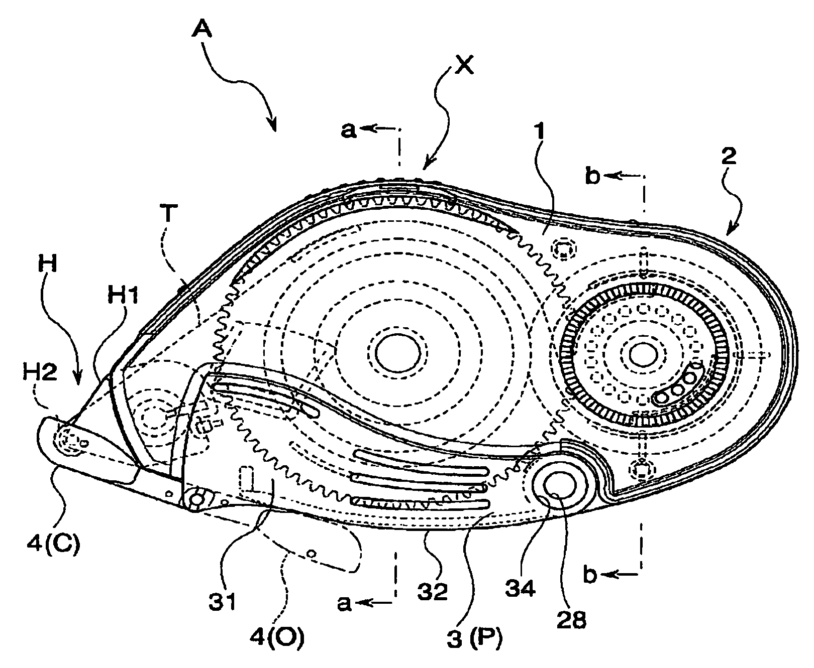
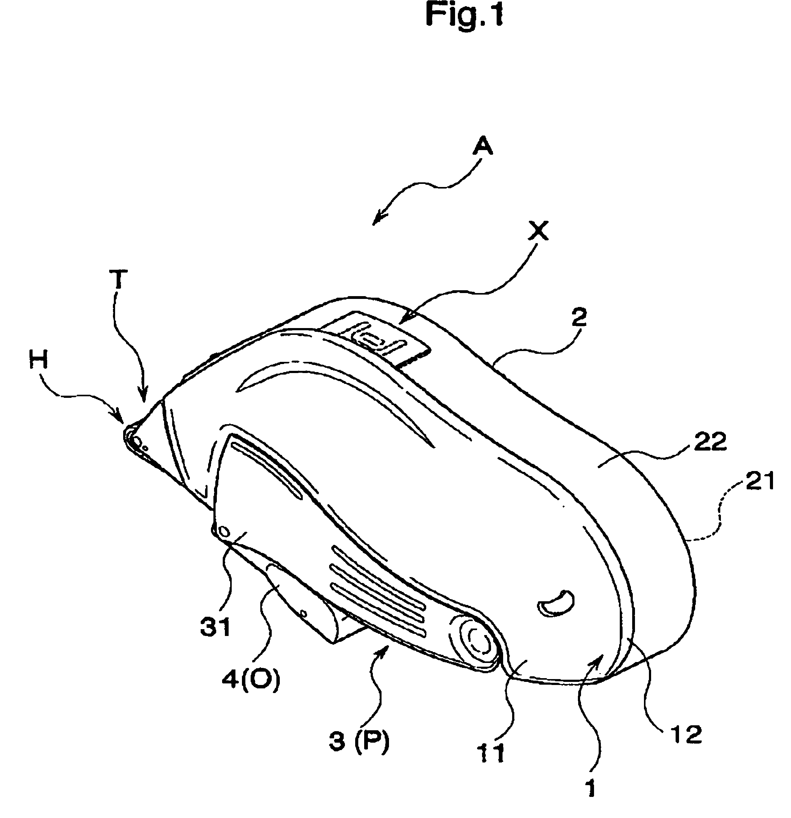
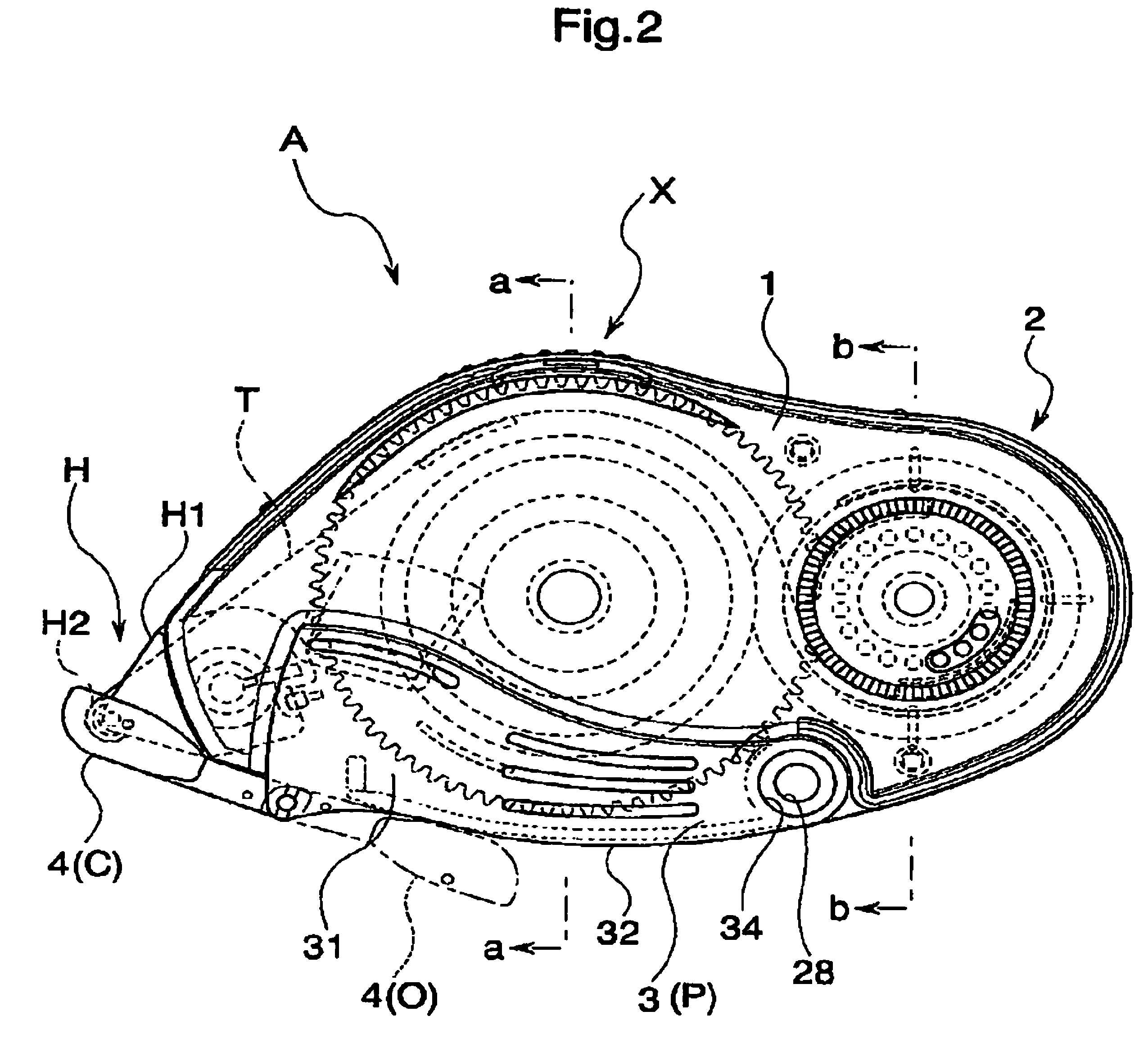
[0020]A transfer tool A in accordance with the embodiment a perspective view of which is shown in FIG. 1 employs a coating tape-shaped glue (hereinafter, refer to as “tape glue T”) as a transferring object, and is used by sticking a glue of the tape glue T delivered per a desired length to a surface of a transferred object such as a slip of paper or the like. In this case, the tape glue T is structured by previously sticking the glue onto one surface of a long and thin tape main body made of a resin. In the present embodiment, the transfer tool A has a first case 1 and a second case 2 which accommodate the glue and a feeding mechanism part feeding the glue and are formed approximately as a half dividing structure, and a holding portion 3 which is outside fitted to a pair of cases 1 and 2, as main constituting parts.

[0021]In this case, the tran...


PUM

PropertyMeasurementUnit
forceaaaaaaaaaa
strengthaaaaaaaaaa
timeaaaaaaaaaa

Abstract

The invention provides a transfer tool which can preferably maintain a shape while improving a strength at a time of using, and has an improved usability. The transfer tool is provided with a first case (1) holding a replacement part including at least a transferring object, a second case (2) detachably engaged with the first case (1) and holding a non-replacement part constituting at least a part of a feeding mechanism part feeding the transferring object to a transferred object, a holding portion (3) outside fitted detachably to a predetermined region of the first case (1) and the second case (2) and capable of holding the first case (1) and the second case (2), and an engagement portion (X) detachably engaging the first case (1) and the second case (2) in a opposite direction of the holding portion (3).

Description

BACKGROUND OF THE INVENTION[0001]1. Field of the Invention[0002]The present invention relates to a refilling type transfer tool used for transferring a transferring object such as a tape glue, a correction tape or the like to a transferred object such as a paper or the like.[0003]2. Description of the Related Art[0004]As this king of refill type transfer tool, there have been considered various structures in which a case having a half dividing structure has a transferring object and a feeding mechanism part for feeding the transferring object out of the case built-in, and a member to be replaced is counterchanged by a new one by separating the case in the case that the transfer tool is finished (for example, refer to Japanese Unexamined Patent Publication No. 2002-178694). The transfer tool disclosed in the publication is structured such that a case is formed by a half dividing structure (in which one is called a first case and the other is called a second case tentatively), the fir...

Claims


Application Information

Patent Timeline
Patent Type & Authority Patents(United States)
IPC IPC(8): B32B15/00B43M99/00
CPCB65H37/007Y10T156/1705Y10T156/1707Y10T156/1746Y10T156/1795
Inventor KAI, KEIJISHIMA, HIDETO
Owner KOKUYO S&T CO LTD
Why Eureka
Try Eureka