
Variable stiffness guidewire

a guidewire and variable stiffness technology, applied in the field of guidewires, can solve the problems of insufficient rigidity of procedures, inability to obviate the need, and the catheter cannot be used to define its own path through the vasculature, etc., and achieve the effect of improving navigability through tortuous body vessels and being sufficiently rigid

Inactive Publication Date: 2011-01-11
CARDINAL HEALTH SWITZERLAND 515 GMBH
View PDF105 Cites 15 Cited by
  • Summary
  • Abstract
  • Description
  • Claims
  • Application Information

AI Technical Summary

Benefits of technology

The present invention provides a variable stiffness guidewire with a flexible distal portion for pre-shaping and improved navigability through tortuous body vessels. The guidewire has a composite structure with a relatively rigid proximal portion and a more flexible distal portion, which is made of a shape memory material. The guidewire also includes a spring with different cross-sectional shapes at different locations, which provides improved stiffness and tip shape retention during stiffening. The invention is applicable to guidewire delivery of catheters to vessels of the human vascular system, but it can also be used for other body lumens.

Problems solved by technology

The path to the diseased site is typically tortuous and may additionally pass through other constricted lumens, so catheters cannot be used to define their own path through the vasculature.
The different body environments in which guidewires must operate create several design complications.
Even proper guidewire selection cannot obviate the need for multiple guidewire usage for some body environments.
Stainless steel is well-suited for procedures requiring the guidewire to be forced through a constricted vessel, but it is not sufficiently flexible for procedures requiring the guidewire to define a tortuous path.
Another problem with known variable stiffness guidewires is that they use springs having a uniform cross-sectional shape.
Most often, the coil spring has a round or circular cross-sectional shape, which performs well for operations requiring flexibility, but not as well for operations requiring more stiffness.
However, flat coil springs are not as flexible as would be desired in operations involving a tortuous vessel pathway.

Method used


Image

  • Variable stiffness guidewire
  • Variable stiffness guidewire
  • Variable stiffness guidewire

Examples


Embodiment Construction

[0021]As required, detailed embodiments of the present invention are disclosed herein; however, it is to be understood that the disclosed embodiments are merely exemplary of the invention, which may be embodied in various forms. Therefore, specific details disclosed herein are not to be interpreted as limiting, but merely as a basis for the claims and as a representative basis for teaching one skilled in the art to variously employ the present invention in virtually any appropriate manner.

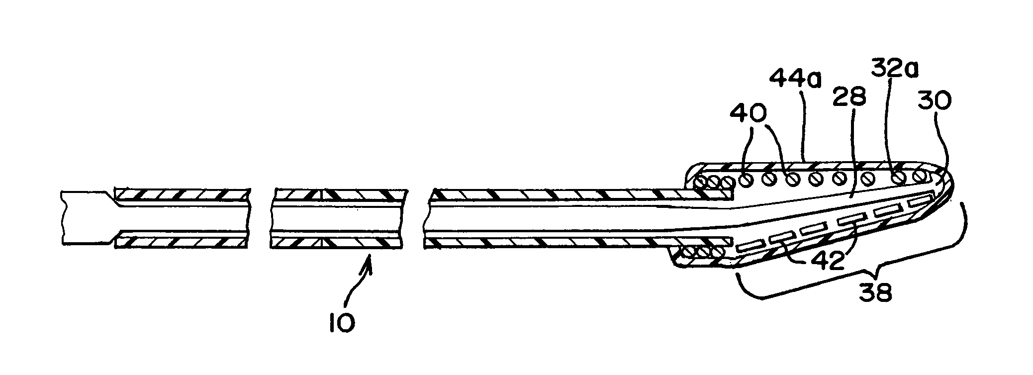
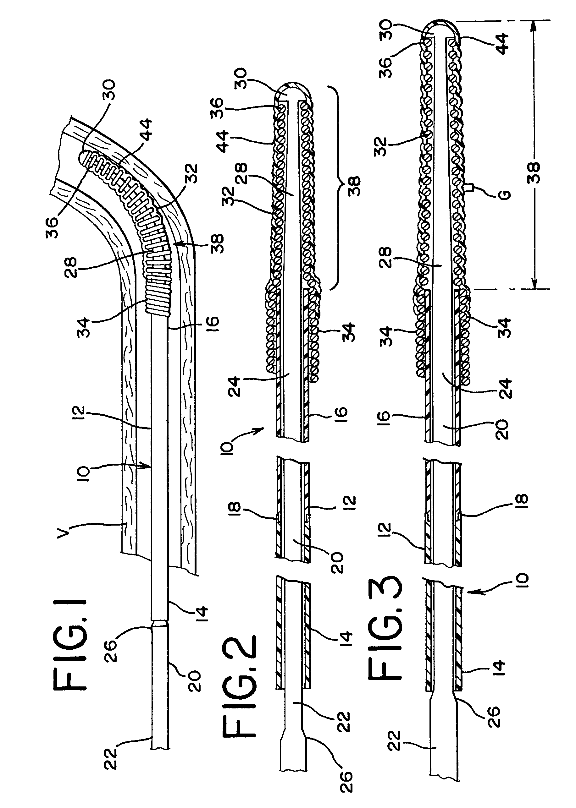
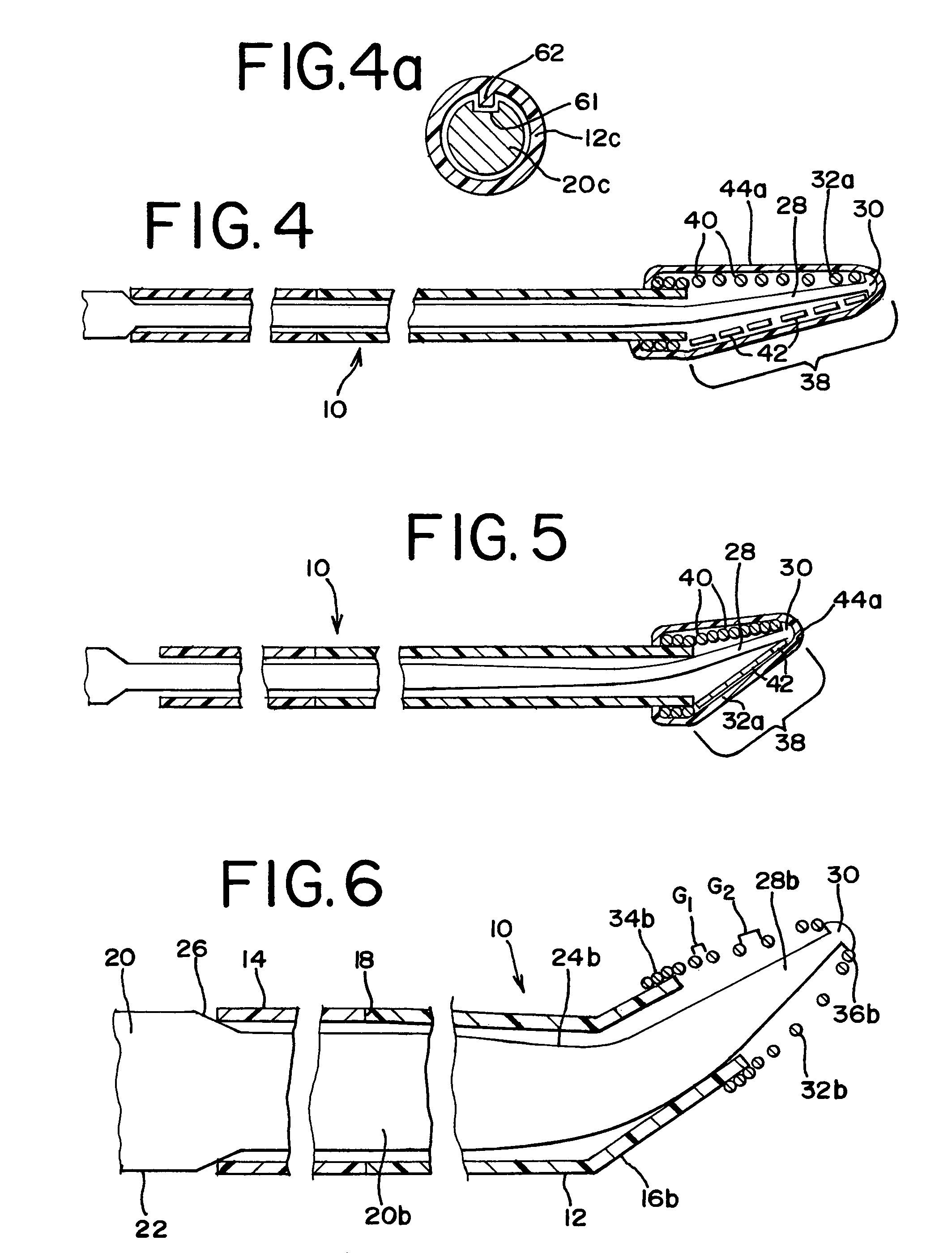
[0022]FIG. 1 illustrates a guidewire 10 in a body vessel V. The guidewire 10 includes a hypotube or tube 12 with a proximal portion 14 and a distal portion 16, which are best shown in FIGS. 2 and 3. The proximal portion 14 and distal portion 16 are made of different materials, typically being separate tubes that are joined at joint 18. The respective proximal and distal portions 14 and 16 preferably have substantially equal respective outer and inner diameters at their location of contact, which fa...


PUM


Abstract

A guidewire navigable through body vessels of a human subject for delivery of a catheter or the like is provided. The guidewire has a tube which receives a corewire that protrudes beyond a distal portion of the tube. The protruding portion of the corewire is surrounded by a spring and shapeable into a curve or arc. The cross-sectional shape of the spring may be varied in order to promote bending flexibility and curvature or to favor curvature of a chosen type. The corewire is axially movable with respect to the tube, which compresses or stretches the spring to change the stiffness of the spring. The tube has a proximal portion comprised of a relatively rigid material, such as stainless steel, while a distal portion is comprised of a more flexible material, such as a nitinol.

Description

FIELD OF THE INVENTION[0001]This invention generally relates to medical devices that are navigable through body vessels of a human subject. More particularly, this invention relates to guidewires used to position a catheter or the like within a body vessel.DESCRIPTION OF RELATED ART[0002]Vessel defects, such as blockages and stenoses, within the human vasculature system are often treated by the intraluminal delivery of treatment fluids or expansion devices and stents. Expansion devices can take any of a number of forms, but are all generally delivered by a flexible catheter that, once properly positioned, deploys the expansion device. The path to the diseased site is typically tortuous and may additionally pass through other constricted lumens, so catheters cannot be used to define their own path through the vasculature. As such, a more rigid guidewire is first passed through the vasculature to the desired site, and then the catheter is passed over the guidewire.[0003]The different ...

Claims


Application Information

Patent Timeline
Patent Type & Authority Patents(United States)
IPC IPC(8): A61B5/00
CPCA61M25/09A61M2025/09083A61M2025/09158A61M2025/09175
Inventor WU, MINAHOJEIBANE, HIKMAT
Owner CARDINAL HEALTH SWITZERLAND 515 GMBH
Learn More