Stent delivery system with nested stabilizer and method of loading and using same

a technology of stabilizer and stent, which is applied in the field of endoluminal grafts or “ stents”, can solve the problems of stent collapsing, low column strength segment which is one which tends to collapse, damage to the stent or incorrect deployment, etc., and achieves the effects of low column strength, low column strength, and convenient use of stents

Inactive Publication Date: 2011-01-11
LIFESHIELD SCI
View PDF35 Cites 95 Cited by
  • Summary
  • Abstract
  • Description
  • Claims
  • Application Information

AI Technical Summary

Benefits of technology

[0012]In accordance with this invention, there is provided a stent delivery system for receiving, endoluminally transporting, and endoluminally deploying an elongated stent for holding open a body lumen, which system facilitates the use of stents with low column strength. The stent delivery system comprises a stent, an overlying sheath, and a stabilizer. The stent has an inner periphery that defines an interior space extending lengthwise along at least a part of the stent, at least one longitudinal segment of which may comprise relatively low column strength (or reduced column strength as compared to other parts of the stent), in that such segment

Problems solved by technology

This inability to transmit longitudinal force may result in such stents collapsing in an accordion fashion as the sheath is retracted or as the stent is ejected by movement of the stabilizer, when the stent is deployed using a standard stabilizer positioned at the proximal end

Method used


Image

  • Stent delivery system with nested stabilizer and method of loading and using same
  • Stent delivery system with nested stabilizer and method of loading and using same
  • Stent delivery system with nested stabilizer and method of loading and using same

Examples


Embodiment Construction

[0028]The invention will next be illustrated with reference to the figures wherein similar numbers indicate the same elements in all figures. Such figures are intended to be illustrative rather than limiting and are included herewith to facilitate the explanation of the apparatus of the present invention.

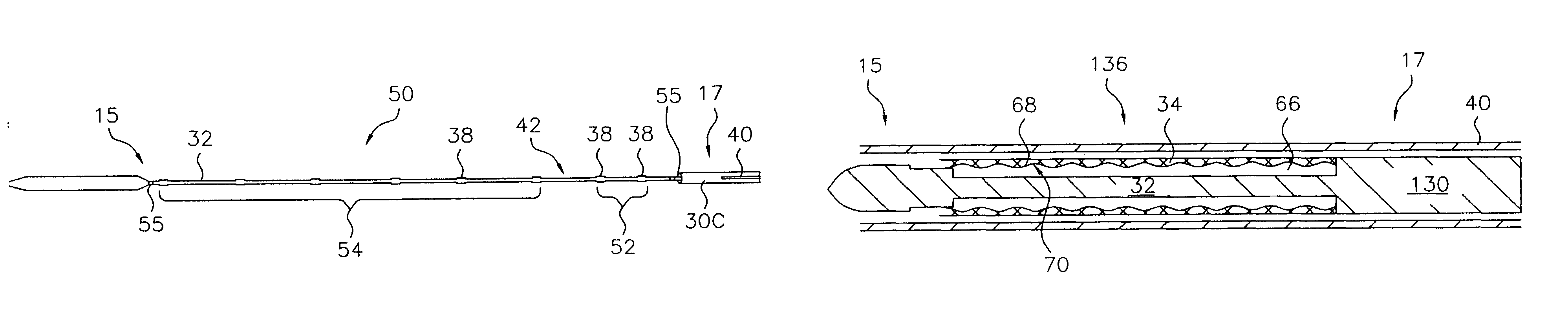
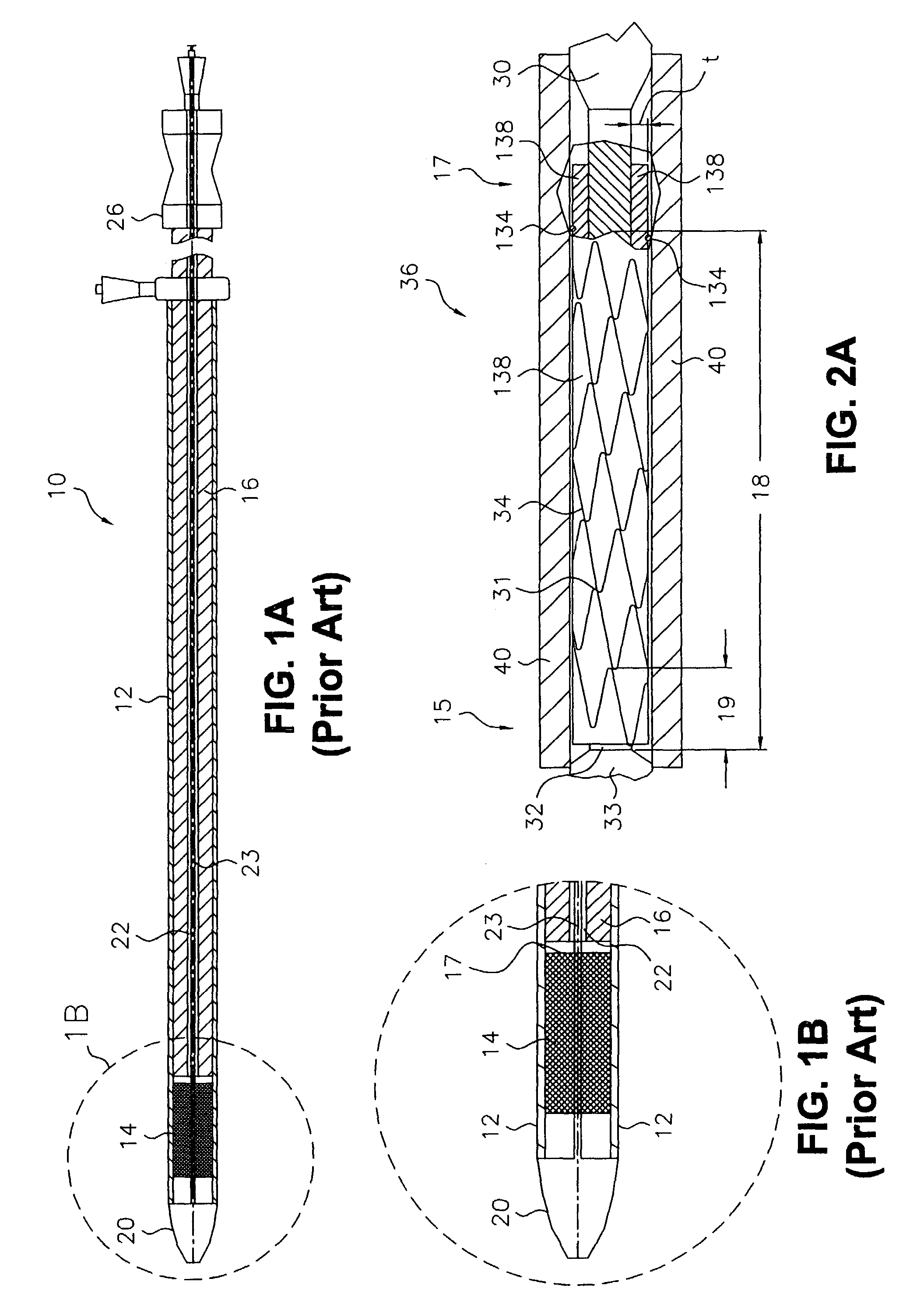
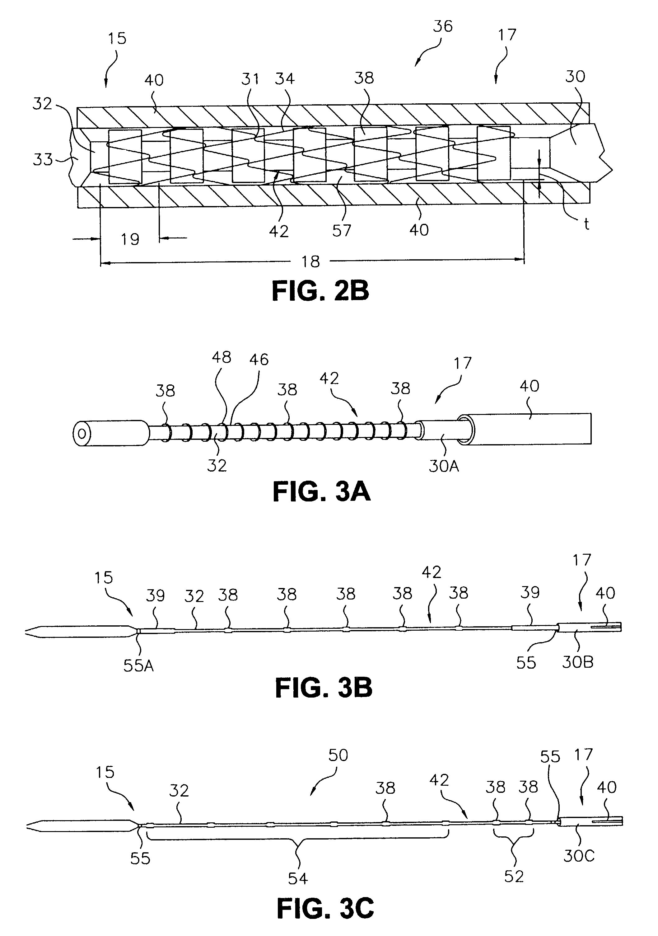
[0029]As shown in FIGS. 2A and 2B, exemplary stent delivery systems 36A and 36B, respectively, of the present invention each include a sheath 40 (shown in longitudinal-section) and a stabilizer 30A and 30B (shown in full) for deploying stent 34 relative to sheath 40. Stent 34 comprises a periphery, such as a wire structure, that defines an interior space therein through which stabilizer 30A or 30B is axially disposed. Stabilizer 30A or 30B comprises an inner core 32 having a surface 42 that underlies (“nests” within) the compressed stent during introduction into the body. Catheter tip 33 is attached to the distal end of stabilizer inner core 32, distal to an exemplary stent 34. As u...


PUM


Abstract

A stent delivery system deploys a stent having an inner periphery that defines an interior space extending lengthwise along at least a part of the stent and comprising at least one segment having relatively low column strength. The stent delivery system comprises a stabilizer which is disposed within the stent interior space and has a surface element adapted to engage the stent inner periphery in a region containing the low-column-strength segment. The surface element may comprise a sleeve or a coating having a high friction surface adapted to transmit adequate shear force to the stent to move the stent relative to the outer sheath upon deployment. Alternatively, or in addition, the surface element can include at least one radial protuberance. The protuberances may comprise rings of various cross-sections, axial lengths, or space sizes therebetween, or may be in the form of discrete barbs, bumps, or inflatable knobs arranged in a ringed configuration or helical pattern about the stabilizer. The stabilizer may also comprise an inner core and a heat-moldable compression sleeve surrounding the inner core, the heat-moldable compression sleeve having an outer surface comprising a plurality of protuberances defined by a thermal imprint of the stent inner periphery on the compression sleeve outer surface. A method for delivering a stent using a stent delivery system as described herein is also disclosed, as is a method for loading a stent and stabilizer having a heat-moldable compression sleeve into a stent delivery system.

Description

[0001]This application is a continuation of U.S. patent application Ser. No. 09 / 574,418, filed on May 19, 2000 now U.S. Pat. No. 6,607,551.CROSS-REFERENCE TO RELATED APPLICATIONS[0002]This application claims priority based upon U.S. Provisional Application Ser. No. 60 / 134,985, filed May 20, 1999, and U.S. Provisional Application Ser. No. 60 / 157,335, filed Oct. 1, 1999.TECHNICAL FIELD[0003]This invention relates generally to endoluminal grafts or “stents” and, more specifically, to stent delivery systems or “introducers”.BACKGROUND OF THE INVENTION[0004]A stent is an elongated device used to support an intraluminal wall. In the case of a stenosis, a stent provides an unobstructed conduit for blood in the area of the stenosis. Such a stent may also have a prosthetic graft layer of fabric or covering lining the inside and / or outside thereof. Such a covered stent is commonly referred to in the art as an intraluminal prosthesis, an endoluminal or endovascular graft (EVG), or a stent-graf...

Claims


Application Information

Patent Timeline
IPC IPC(8): A61F2/84A61F2/82A61F2/06
CPCA61F2/95A61F2002/9583A61F2002/9665
Inventor SULLIVAN, JASON R.KELLER, JOHNKETTERER, MATTHEW S.DIMATTEO, KRISTIAN J.BETTUCHI, MICHAEL J.GOLDS, ELLEN
Owner LIFESHIELD SCI
Why Eureka
Try Eureka