
Network node and associated methodology of expanding a network topology through peer selection

a network topology and peer selection technology, applied in the field of network topology generation, can solve the problems of reducing data transfer efficiency in a newly generated network and considerable delay

Inactive Publication Date: 2011-01-11
NTT DOCOMO INC
View PDF11 Cites 0 Cited by
  • Summary
  • Abstract
  • Description
  • Claims
  • Application Information

AI Technical Summary

Benefits of technology

[0012]In viewing of the foregoing, it is an object of the present Invention to provide a network topology generation method and a node which can reduce a network delay fairly and minimally, upon generating a new network topology, by considering a network condition in a physical layer

Problems solved by technology

However, In the conventional method for generating a network topology a network condition in a physical layer is not considered, upon generating a new network topology.
Therefore, there is a possibility that a network delay is considerably large between adjacent nodes in a logical layer, and there is a possibility that data transfer efficiency is reduced in a newly generated network.

Method used


Image

  • Network node and associated methodology of expanding a network topology through peer selection
  • Network node and associated methodology of expanding a network topology through peer selection
  • Network node and associated methodology of expanding a network topology through peer selection

Examples


Embodiment Construction

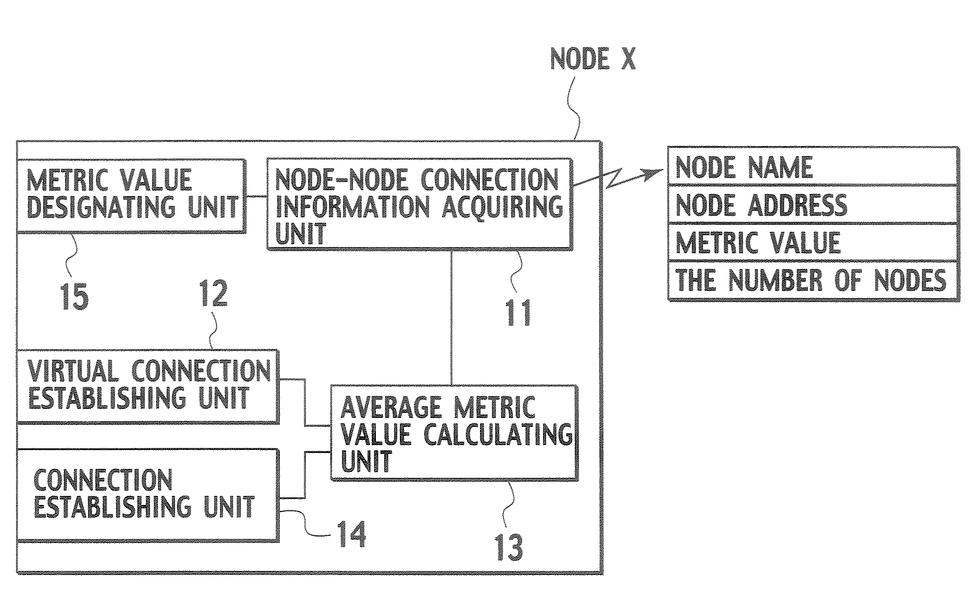
[0037]Referring to FIGS. 6A and 6B, a configuration of a node for achieving a network topology generation method according to a first embodiment of the present invention will be described In this embodiment, a node X is configured to be able to newly loin a network including a plurality of nodes A to D.

[0038]As shown in FIG. 6A, a node X according to this embodiment includes a node-node connection information acquiring unit 11 a virtual connection establishing unit 12, an average metric value calculating unit 13, a connection establishing unit 14 and metric value designating unit 15.

[0039]The node-node connection information acquiring unit 11 is configured to acquire, from any node forming the network (for example, node A), node-node connection information of adjacent nodes (for example, nodes B to D) to the any node. Note that, the node-node connection information includes a “node name (node ID)” for identifying the adjacent node, a “node address (for examples an IP address)” of th...


PUM


Abstract

The network topology generation method can reduce a network delay fairly and minimally, upon generating a new network topology, by considering a network condition in a physical layer. The network topology generation method includes establishing a virtual connection between the new node and each of the plurality of nodes; calculating an average metric value of routes from the new node to the plurality of nodes via each of the virtual connections; and establishing a connection between the new node and the node to which the virtual connection having the smallest average metric value is established, so that the new node joins the network.

Description

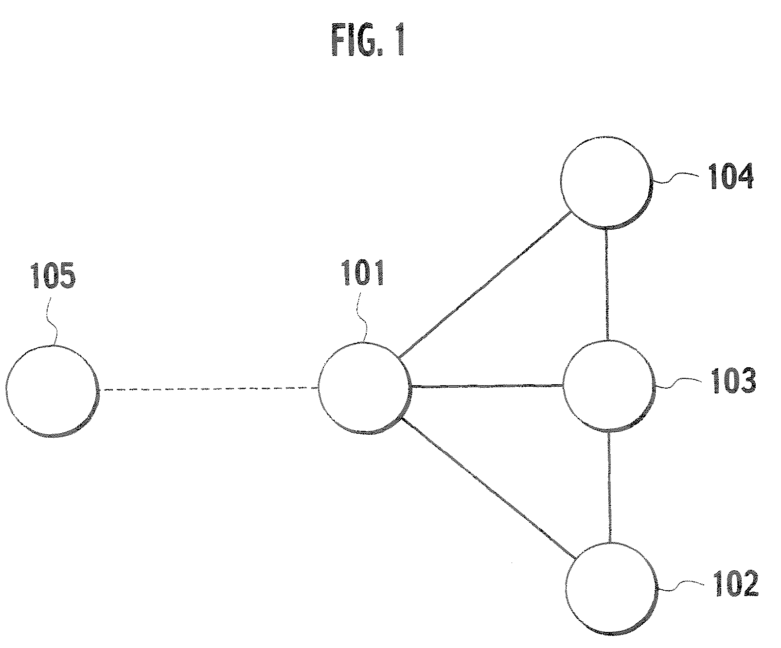
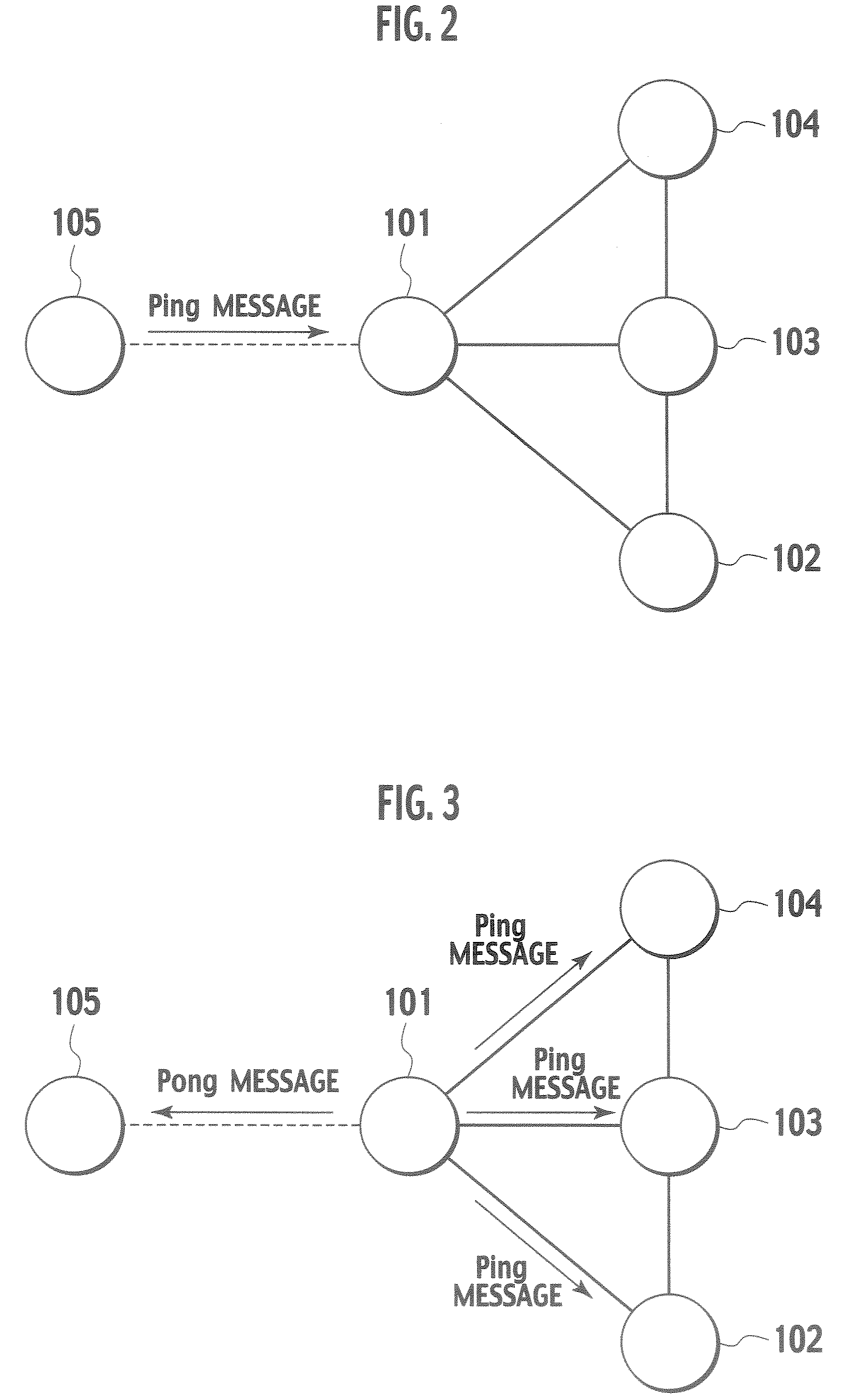
TECHNICAL FIELD[0001]The present invention relates to a method for generating a network topology in which a new node joins a network formed by a plurality of nodes. The present invention also relates to a node which newly joins a network formed by a plurality of nodes.BACKGROUND ART[0002]Referring to FIGS. 1 to 5, a conventional method for generating a network topology (a method used in the “Gnutella”) will be explained. To be more specific, an operation in which a node 105 newly joins a network including nodes 101 to 104.[0003]First, as shown in FIG. 1, the node 105 selects a node 101 which IP address or URL the node 105 knows, among from a plurality of nodes 101 to 104 which forms the network, so as to establish a connection with the node 101.[0004]Second, as shown in FIG. 2, the node 105 transmits a PING message including an IP address of the node 105 to the node 101.[0005]Third, as shown in FIG. 3, the node 101 returns a PONG message including an IP address of the node 101 to th...

Claims


Application Information

Patent Timeline
Patent Type & Authority Patents(United States)
IPC IPC(8): G06F15/173H04L45/02H04L45/121
CPCH04L45/02H04L45/123H04L67/1053H04L67/1046H04L67/104
Inventor WAN, HAOYIISHIKAWA, NORIHIRO
Owner NTT DOCOMO INC
Learn More