Rotary knob for electrical system

a technology of electrical system and rotary knob, which is applied in the direction of contact mechanism, mechanical control device, instruments, etc., can solve the problem of driving the knob in an inopportune manner

Active Publication Date: 2011-01-18
SCHNEIDER ELECTRIC IND SAS
View PDF11 Cites 35 Cited by
  • Summary
  • Abstract
  • Description
  • Claims
  • Application Information

AI Technical Summary

Benefits of technology

[0006]The purpose of the invention, in a rotary knob of the type described, is to overcome the disadvantages of the prior art by proposing a knob providing satisfactory guidance of the rotary part using means conferring the knob with minimal dimensions, in particular height, and facilitating assembly.
[0017]According to a first variant embodiment, the sealing device comprises a guard ring intended to retain the sensitivity ring and housed in the stepped annular space of the body. The head of the hand grip can be provided with a reentrant annular rim which is housed in the staged annular space of the body. Thus the annular rim of the hand grip and the guard ring define between them a first radial annular interstice between the flange and the annular rim and a second radial annular interstice between the annular rim and the cylindrical skirt, the two interstices in series forming a sealing chicane. The guard ring contributes to forming a barrier against the introduction of dust, polluting elements or projections inside the body of the rotary knob, and the two interstices together avoid, in normal conditions of use, having to make use of a sealing gasket of large diameter.
[0019]For purposes of compactness, the compression spring housed in the cup can advantageously have a height of substantially the same order as the height of the cylindrical sleeve.

Problems solved by technology

These knobs sometimes have the disadvantage that, although the maneuvering member is placed in one of its functional positions, a slight force applied to that member can suffice to make a notch of the cam jump and to drive the knob in an inopportune manner.

Method used


Image

  • Rotary knob for electrical system
  • Rotary knob for electrical system
  • Rotary knob for electrical system

Examples


first embodiment

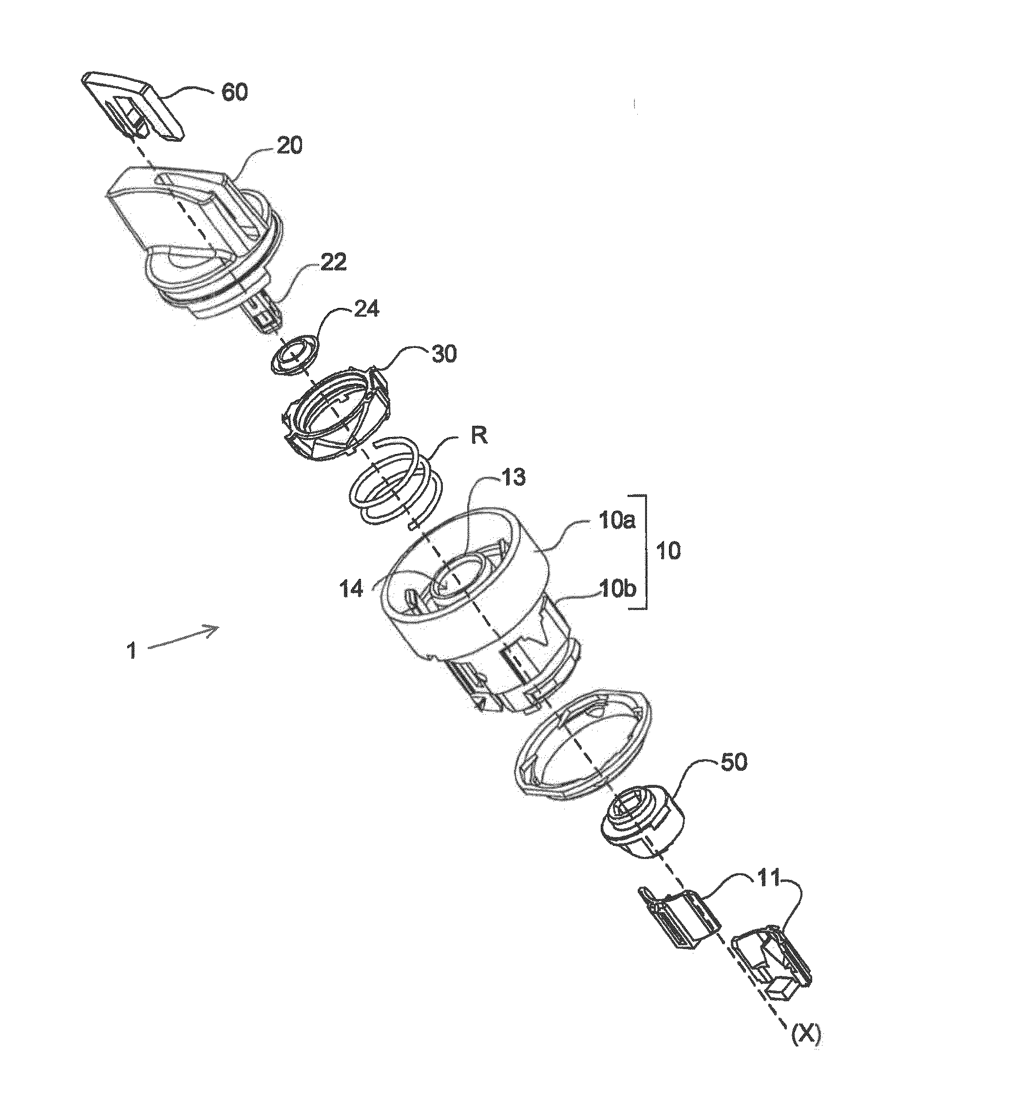
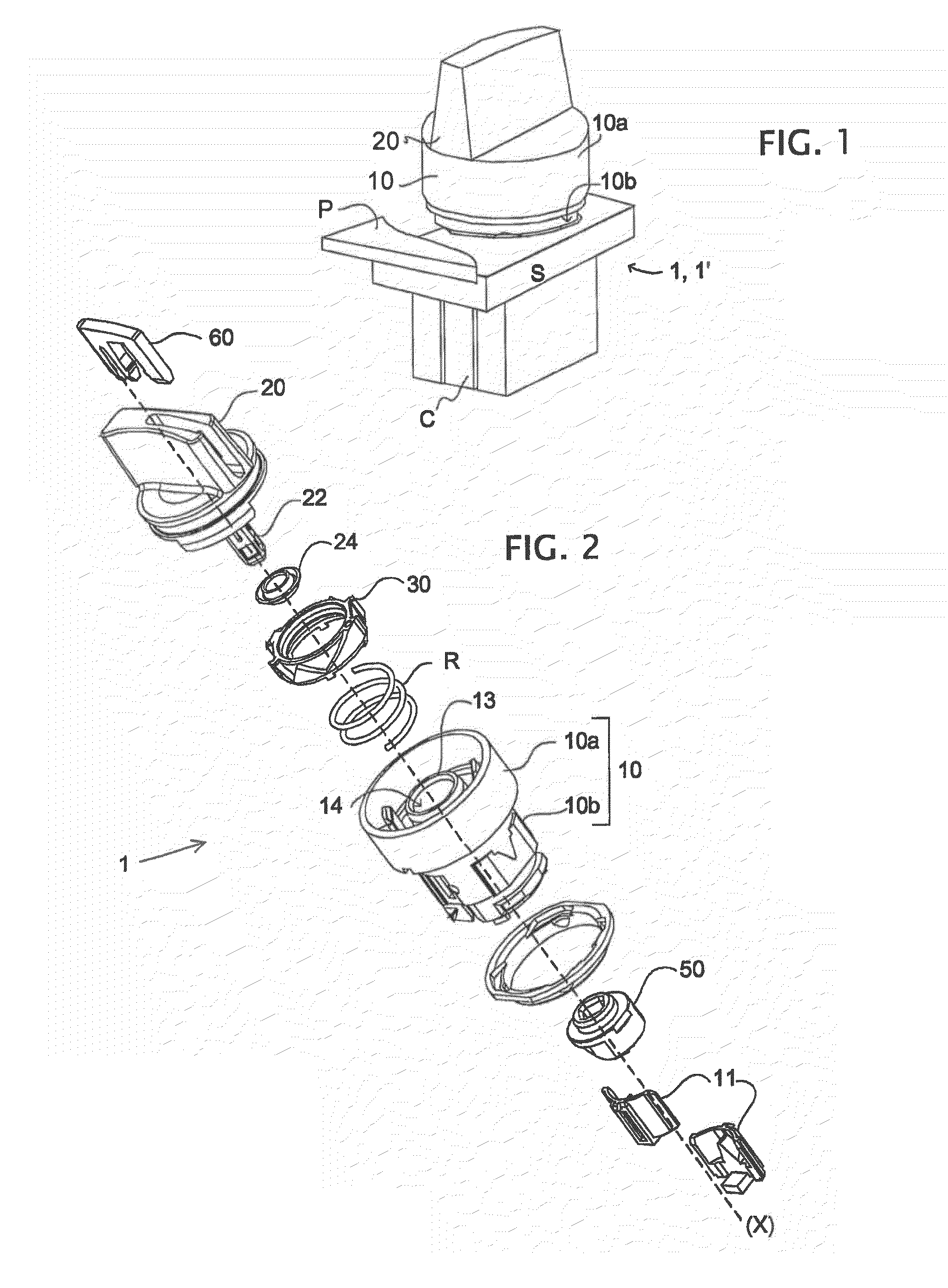
[0038]In the first embodiment, the body 10 comprises a sliding sensitivity ring 30 translationally acted upon by the compression spring R. The compression spring R is applied on the one hand against the bottom of the cup 15 and on the other hand against the sensitivity ring 30 in order to act upon the latter axially.

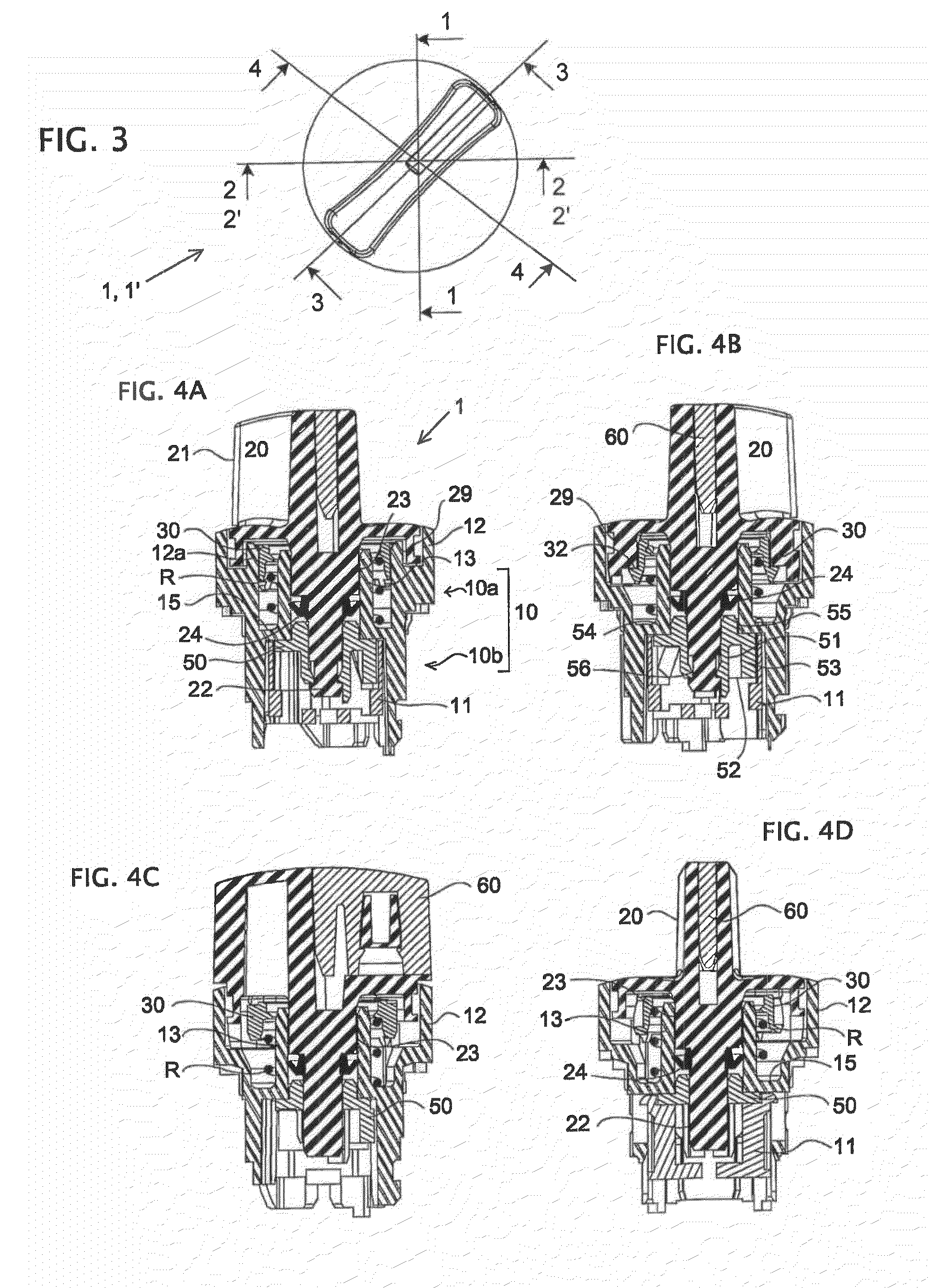
[0039]The hand grip 20 has a grasping head 21 having the shape of a wing formed in an axial plane. The hand grip 20 furthermore comprises a central shank 22 which is connected to the head and extends axially in order to traverse the central opening 14, the driving part 50 being fixed by interlocking to the shank 22.

[0040]The hand grip 20 has a centering seat 23 (FIG. 6) which is applied against the internal face of the sleeve 13 and which has a groove or an annular shoulder in order to receive a lip seal 24 providing good fluid-tightness with the internal face of the sleeve. A groove 29 (FIGS. 4A to 4D) provided on the periphery of the grasping head 21 of the hand grip i...

second embodiment

[0049]In the invention, the rotary knob 1′ is called a return knob and uses a torsion spring R′ in replacement of the compression spring R. The latter is fixed on the one hand to the bottom of the cup 15 and on the other hand to the hand grip 20 in order to return the latter in a rotary manner.

[0050]In this embodiment, shown in FIGS. 7 and 8, the body has an intermediate internal flange 17 separating the cup 15 from the previously defined annular space 16. The hand grip 20 has a reentrant skirt 28 in the annular space 16. The presence of the sleeve 13 and of the intermediate flange surrounding the spring R′, combined with the presence of the reentrant skirt 28 of the hand grip, produce the sought fluid-tightness. The other features of the rotary return knob 1′ are identical to those of the rotary knob 1 with positions.


PUM


Abstract

A rotary knob for an electrical system includes a body containing a rotary maneuvering member which actuates a cam-driving part and bears one or more electrical units. A cup is defined between an outer cylindrical flange of the body and an inner cylindrical sleeve, and contains a spring either of a helical type for urging a sliding ring separate from the driving part, or of a torsion type to return the maneuvering member. The ring provides a sensitivity function. The cylindrical sleeve defines in a central opening thereof a centering seat of the shank of the maneuvering member.

Description

BACKGROUND OF THE INVENTION[0001]I. Field of the Invention[0002]The present invention relates to a rotary knob for an electrical system, comprising a body on which can be mounted a rotary maneuvering member, in particular a hand grip or a rotor controlled by a key, and of housing a driving part for switching contacts.[0003]II. Description of Related Art[0004]In conventional rotary knobs, the maneuvering member is provided with a shank for moving the driving part, and the body also serves as a support for at least one electrical contact block, switchable in response to the rotation of the maneuvering member via at least one axially moving slider. The maneuvering member is mounted on the body such that it rotates about an axis with a limited angular movement, in order to assume at least two functional positions, maintained or transitory. Rotary knobs of this type are well known (see for example the documents DE 34 12 518 and DE 35 41 390). The maneuvering member is locked in rotation ...

Claims


Application Information

Patent Timeline
Patent Type & Authority Patents(United States)
IPC IPC(8): G05G1/10G05G5/06F16H53/00H01H3/08H01H11/00H01H19/635H01H21/08H01H21/50
CPCH01H19/6355H01H11/0006H01H21/08Y10T74/20636Y10T74/2084Y10T74/2107H01H21/50
Inventor DA DALT, HUGUESTHIZON, PATRICEFRUCHARD, BERTRAND
Owner SCHNEIDER ELECTRIC IND SAS
Why Eureka
Try Eureka