Forklift trucks

a technology for forklifts and trucks, applied in the field of forklifts, can solve problems such as reducing overall strength and integrity, and achieve the effect of reducing the extent of rearward projection and reducing the rearward projection of the wheel

Active Publication Date: 2011-01-18
MOFFETT RES & DEV
View PDF18 Cites 5 Cited by
  • Summary
  • Abstract
  • Description
  • Claims
  • Application Information

AI Technical Summary

Benefits of technology

[0007]In contrast to systems which propose folding the entire chassis the present invention achieves a reduction in truck length by retracting a rear wheel mounted at an end opposite to the forks of the truck. When the forklift truck is designed to be carried on the rear of another vehicle using the forks to mount the truck to that vehicle, the tractable wheel will normally be the rearmost protruding element of the combination. Retraction of that wheel does not significantly alter the balance of the truck but it does reduce the chance of damage to the wheel by a following or passing vehicle or when reversing.
[0008]This reduces the rear projection which in turn minimises tail swing and reduces the overall length of the transport vehicle.
[0013]In a preferred embodiment, the wheel is connected to said mounting plate by means of an arm to which the wheel is rotatably connected at the wheel hub, and wherein said arm is mounted by a swivel mounting to said mounting plate thereby enabling said wheel to be steered relative to the plate.
[0015]Preferably, said wheel is provided with a steering mechanism for rotating the plane of the wheel relative to the body and furthermore, said wheel is preferably mounted on the body with sufficient freedom to be rotated by the steering mechanism when the wheel is in its storage position by substantially 90 degrees from a normal straight-ahead position. By enabling the retraction movement to occur in combination with the rotation of the steering through 90 degrees, the wheel's rearward projection can be reduced even further.
[0016]It is particularly preferred, in this option, to rotate the steering in that direction which most reduces the extent of rearward projection. Thus where a motor or a mounting arm is mounted on one side of the wheel (causing a protrusion on that side) the wheel is preferably steered through 90 degrees to conceal that protrusion from projecting rearwardly.

Problems solved by technology

Such forklift trucks provide the advantage that the shorter body length makes the transport vehicle more stable during travel, but this is achieved by having to make the overhead chassis structure of the truck adjustable, at increased expense and with the possibility of reduced overall strength and integrity.

Method used


Image

  • Forklift trucks
  • Forklift trucks
  • Forklift trucks

Examples


Embodiment Construction

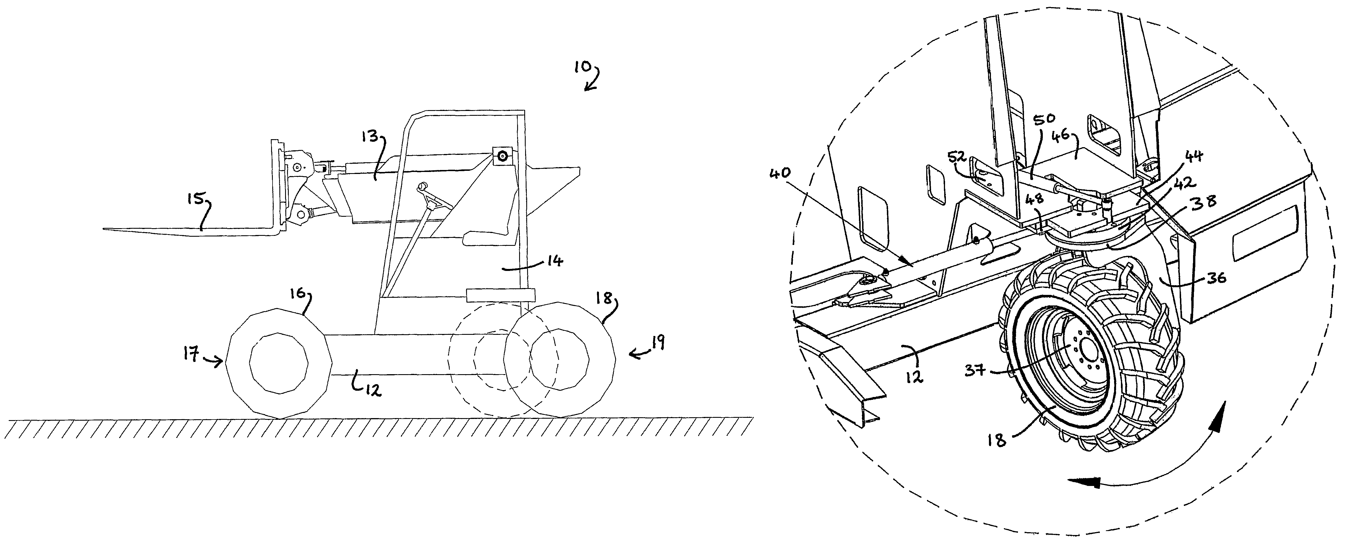
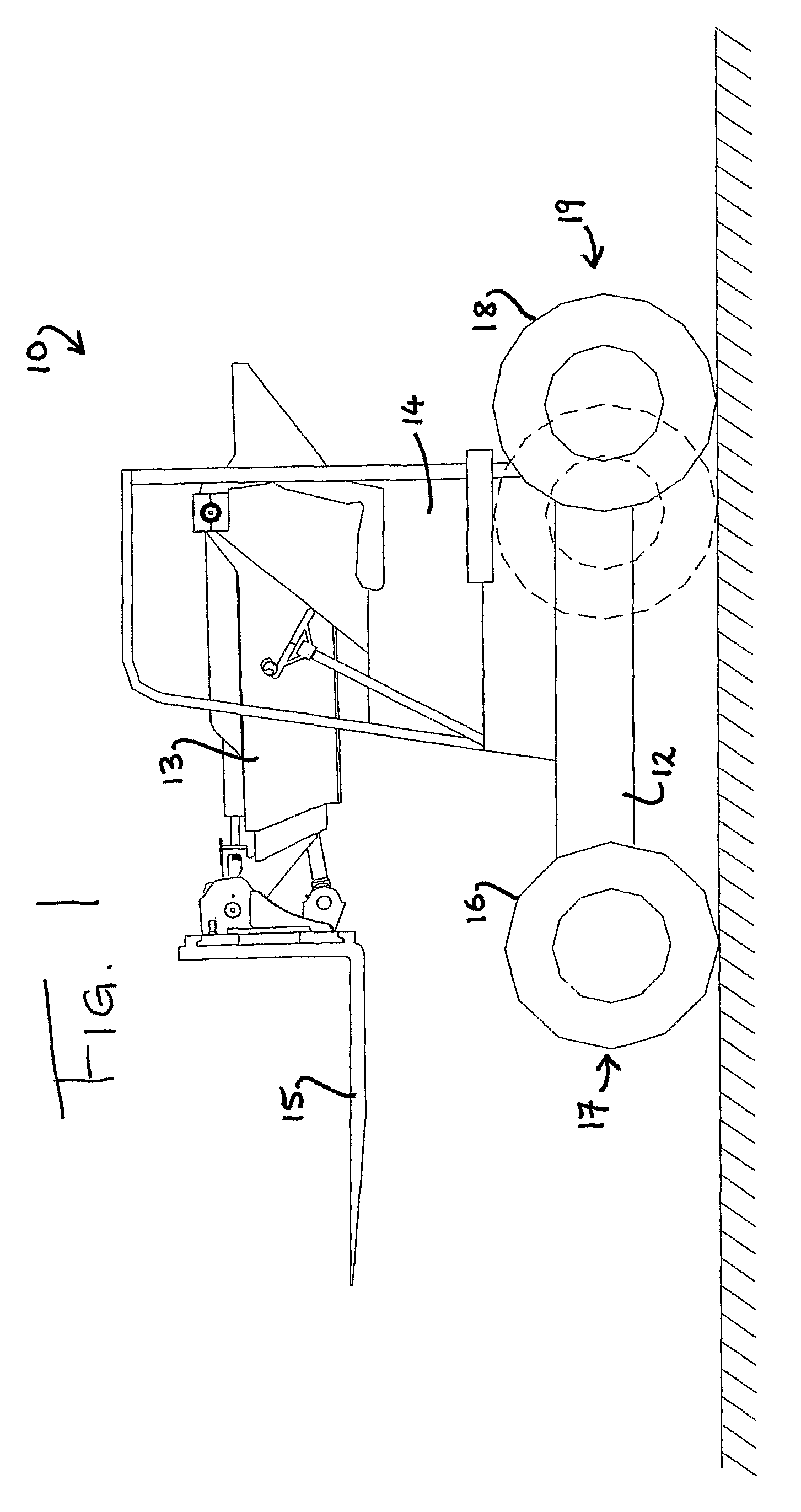
[0023]FIG. 1 is a side elevation of a forklift truck, indicated generally at 10, having a chassis 12, a driver cab 14, a pair of front wheels 16 (the nearest of which can be seen in FIG. 1) at a front end of the forklift truck 10, and a single rear wheel 18 at a rear end 19 of the forklift truck 10. The driver cab is offset on one side of the front-to-rear centre line of the chassis and is situated at the side from which the view of FIG. 1 is taken. A telescopic boom 13 carrying a set of forks 15 is offset on the other side of the centre line (behind the cab in the view of FIG. 1). The forks are adapted to manipulate a load at the front end 17 of the forklift truck. This general arrangement of chassis, offset cab and offset telescopic boom is well known in the field of truck mounted forklifts.

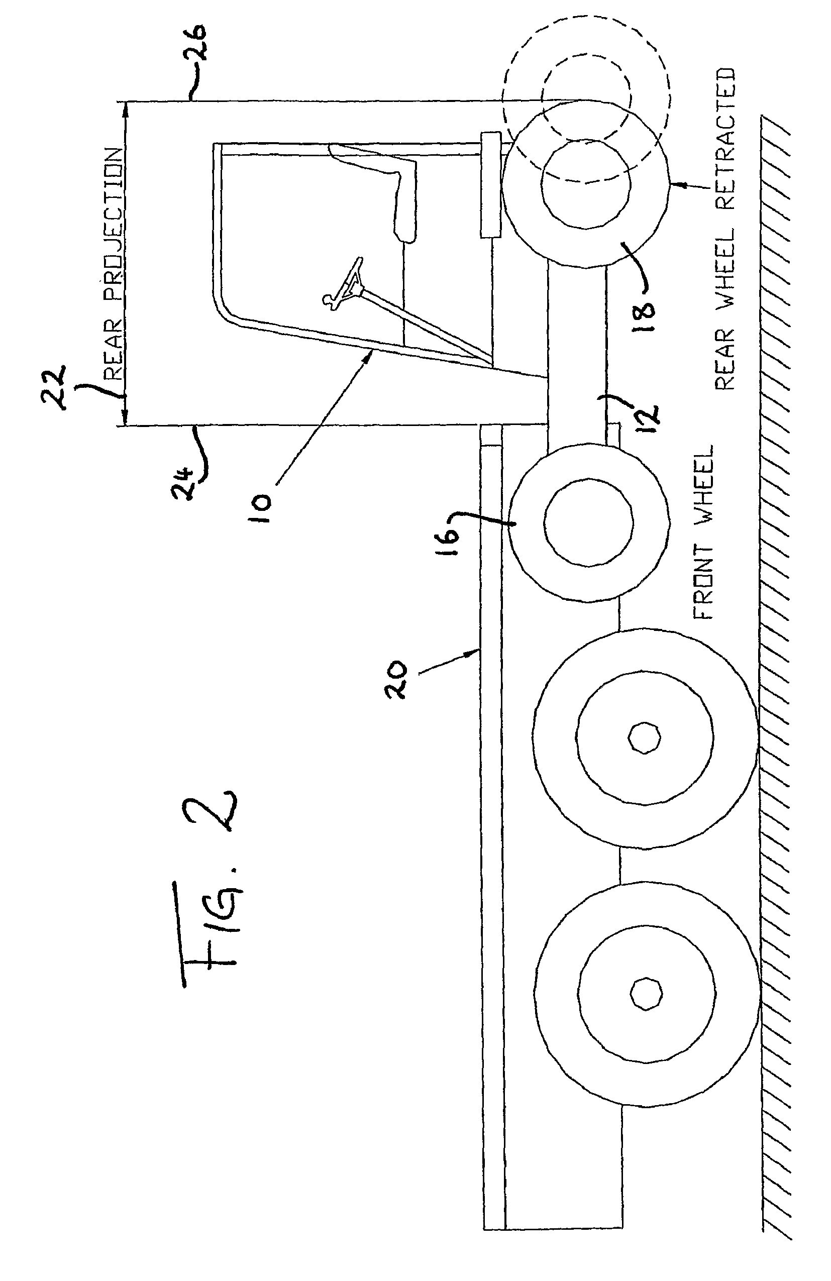
[0024]As shown in FIG. 2, the forklift truck 10 is adapted to be coupled to and carried by a heavy goods vehicle 20. This is achieved by inserting the forks (not shown) into a receiving compart...


PUM


Abstract

A forklift truck (10) comprising a truck body, a fork mechanism at one end of the body, and at least one wheel (18) at an opposite end of the body, said at least one wheel (18) being mounted on the body for translational movement relative to the body between a working position and a storage position.

Description

RELATED APPLICATIONS[0001]The subject application is a U.S. National Stage application that claims the priority of International Application No. PCT / IE2006 / 000061, filed on 02 Jun. 2006.TECHNICAL FIELD[0002]This invention relates to forklift trucks, and in particular to forklift trucks designed to be carried on another vehicle of the type generally known as “truck mounted forklifts”.BACKGROUND ART[0003]Forklift trucks designed to be carried on the rear of a vehicle are well known. Such forklift trucks are usually stowed by securing the forks of the forklift truck to the body of the vehicle and then elevating the body of the forklift truck relative to the forks so that the forklift truck body is lifted off the ground for travel.[0004]U.S. Pat. No. 5,482,141 describes a forklift truck of this type in which the forklift truck has an overhead chassis structure which can be converted between a working configuration and a stowage configuration. In the stowage configuration the hinged over...

Claims


Application Information

Patent Timeline
Patent Type & Authority Patents(United States)
IPC IPC(8): B62D61/12
CPCB66F9/07563
Inventor MCVICAR, MARTINMOFFETT, ROBERTHALL, MEREDITHWHYTE, MARK
Owner MOFFETT RES & DEV
Why Eureka
Try Eureka