Base for underwater camera

a technology for underwater cameras and bases, applied in closed circuit television systems, television systems, instruments, etc., can solve problems such as insufficient approach, insufficient control of rotational displacement, and significant stress on users

Inactive Publication Date: 2011-01-18
INON
View PDF2 Cites 12 Cited by
  • Summary
  • Abstract
  • Description
  • Claims
  • Application Information

AI Technical Summary

Benefits of technology

[0013]It is therefore an object of this invention to eliminate these problems of prior art technologies by providing an improved base for an underwater camera, which can be used for different housings of different types, not causing its fixing screw to become loose during underwater photography while the user is diving, and allowing the housing to be securely affixed to the base.

Problems solved by technology

External flash lamps are used in underwater photography because the quantity of available light is often insufficient.
Since the arm 3 and the external flash lamp at its tip are very heavy, however, this approach has been proved insufficient for dependably preventing the rotational displacement.
Another problem associated with the conventional general-purpose base 1 has been that the loosened screw must be tightened frequently while the user is holding the equipment while being engaged in underwater photography, causing a significant stress on the user while diving.

Method used


Image

  • Base for underwater camera
  • Base for underwater camera
  • Base for underwater camera

Examples


first embodiment

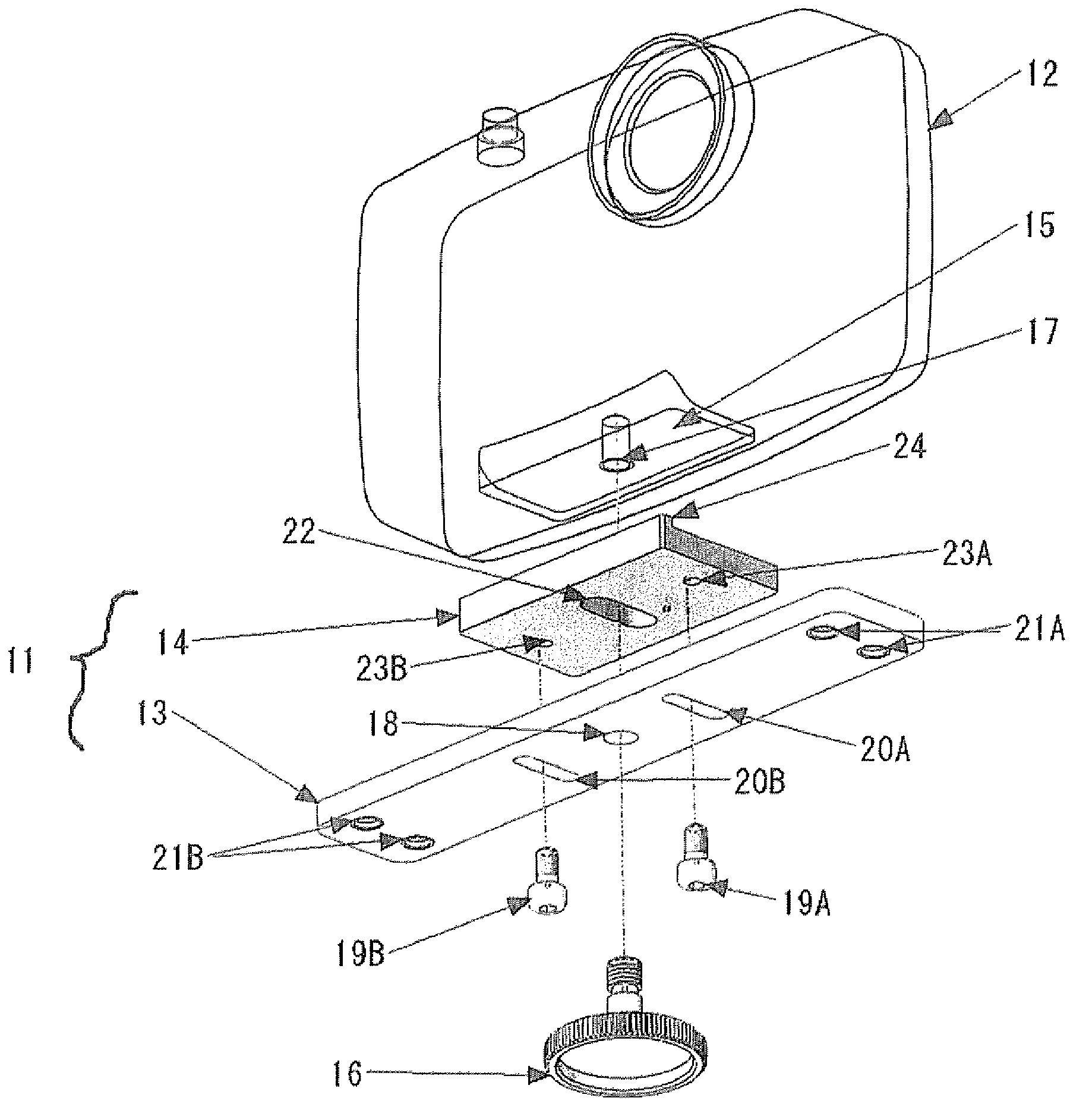
[0050]FIG. 5 is a diagonal view for explaining the structure of a base according to this invention, FIG. 6 is a diagonal exploded view of the same base as seen from below, and FIG. 7 is a diagonal exploded view of the same base as seen from above. A situation in which an arm is attached to the base through a grip will be explained with reference to these figures. It is to be noted that the main body of the camera is omitted from FIG. 7, and the grip and the arm are omitted from FIGS. 5-7.

[0051]In FIGS. 5-7, numeral 11 indicates the base, and numeral 12 indicates a watertight camera housing. The base 11 comprises an elongated planar main body 13 and a planar mobile holder plate 14 which is shorter than the base main body 13 in the longitudinal direction.

[0052]The bottom part of the housing 12 is provided with a pedestal 15 for fastening to the base 11, and a camera-fixing screw hole 17 is formed near the center of this pedestal 15 for accepting a fixing screw 16. This screw hole 17 m...

fifth embodiment

[0077]The base 11 according to the invention is fastened as the protrusion 48 is pressed against the pedestal 15 but the position of the housing 12 may be reversed in the forward-backward direction such that it may be fastened as described above.

[0078]With the base 11 thus structured, too, the housing 12 can be fastened to the base 11 securely without causing any rotational displacement.

[0079]FIG. 19 shows a large camera housing in a fixed condition.


PUM


Abstract

A base, securely attachable to any type of watertight housing for an underwater camera without causing rotational displacement during its use for underwater photography, includes an elongated main body and a holder plate disposed on the main body which is transversely movable. The base has a protrusion for preventing transverse motion of a pedestal or a leg structure on the housing. A pair of set screws is provided in addition to a fixing screw that is passed through a fixing hole through the base main body to fasten the base to the camera housing. The base main body has a fixing hole for the fixing screw and a pair of elongated holes for passing the set screws so as to be transversely movable. The holder plate has an elongated hole for passing the fixing screw so as to be transversely movable and screw holes for engaging the set screws.

Description

[0001]This application claims priority on Japanese Patent Application 2008-271354 filed Oct. 21, 2008.BACKGROUND OF THE INVENTION[0002]This invention relates to a base for fastening and carrying thereon an underwater camera contained inside a waterproof camera housing as it is being used for flash lighting, serving to attach thereto an arm having an external flash light provided at its tip.[0003]External flash lamps are used in underwater photography because the quantity of available light is often insufficient. Since water contains small dust particles such as grains of sand as well as planktons that float around, external lamps are often placed away from a camera with its waterproof housing that surrounds it (hereinafter referred as an “underwater camera”) by distances of from ten and some centimeters to several tens of centimeters such that these dust particles, etc. will not appear conspicuously on the obtained image. For this reason, it has been known (as disclosed, for example...

Claims


Application Information

Patent Timeline
Patent Type & Authority Patents(United States)
IPC IPC(8): G03B17/00G03B17/08
CPCG03B17/02
Inventor INOUE, AKIHIDE
Owner INON
Why Eureka
Try Eureka