Actuator with symmetric positioning

a symmetric positioning and actuator technology, applied in the field of actuators, can solve the problems of no accuracy fluctuation, rapid production of actuators, reciprocating oscillations, etc., and achieve the effects of simple production steps, guaranteed stability, and inexpensive actuators

Inactive Publication Date: 2011-01-18
PANASONIC CORP
View PDF14 Cites 4 Cited by
  • Summary
  • Abstract
  • Description
  • Claims
  • Application Information

AI Technical Summary

Benefits of technology

[0034]According to the present invention, backlining allows a first conductive portion and a second conductive portion of a second movable section to be stabilized in an electrically insulated state. As a result, the first conductive portion and the second conductive portion can be surely stabilized. Moreover, since it is unnecessary to embed something in any trench between the first conductive portion and the second conductive portion, the production steps of the actuator can be simplified and an inexpensive actuator can be provided.
[0035]Moreover, in one embodiment, the actuator includes a mirror section so that a bi-axial pivoting type resonant mirror device is obtained.
[0036]Moreover, in one embodiment, a dummy trench is formed at a point symmetric position from a trench between the first conductive portion and the second conductive portion of the second movable section, whereby a weight imbalance of the second movable section can be minimized.
[0037]Moreover, in one embodiment, the first movable section includes electrode combteeth extending in a direction which is parallel to the pivot axis of the first movable section, and the second movable section includes electrode combteeth extending in a direction which is parallel to the pivot axis of the second movable section. As a result, the first and second movable sections can be driven to greater pivot angles.

Problems solved by technology

Moreover, an oscillating mirror device has a single reflection surface, and therefore suffers no fluctuations in accuracy like those of a polygon mirror having a plurality of faces.
Moreover, the operation of an oscillating mirror device is a reciprocating oscillation, which can be made rapid.

Method used


Image

  • Actuator with symmetric positioning
  • Actuator with symmetric positioning
  • Actuator with symmetric positioning

Examples


Embodiment Construction

[0079]Hereinafter, with reference to the drawings, an embodiment of the present invention will be described.

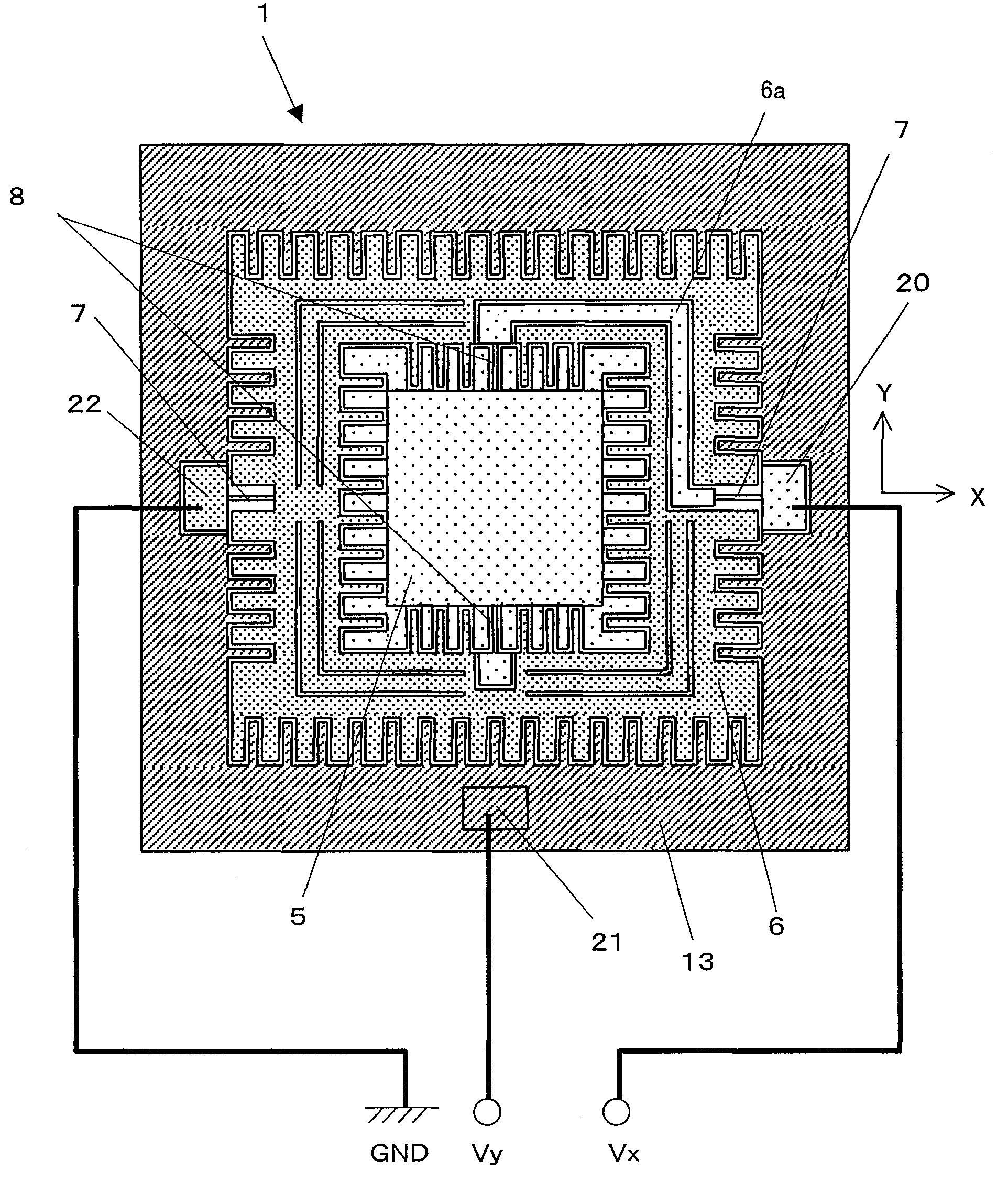
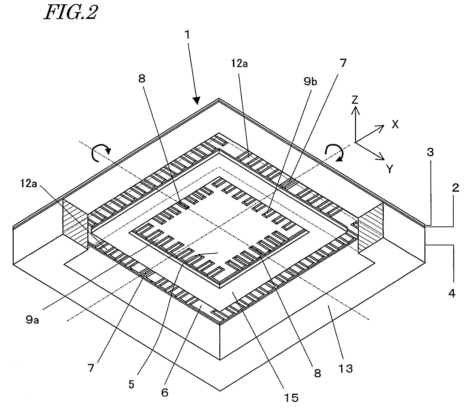
[0080]First, with reference to FIG. 1, an actuator according to the present embodiment will be described. FIG. 1 is a perspective view showing a resonant mirror device 1, which is an actuator of the present embodiment.

[0081]The resonant mirror device 1 is produced by processing a wafer in which two silicon layers are bonded via an insulating layer 2 of silicon oxide (SiO2), i.e., a so-called SOI (Silicon On Insulator) wafer, for example.

[0082]Among the two silicon layers, a first silicon layer is doped with an n type impurity such as phosphorus (P) or arsenic (As) or a p type impurity such as boron (B) so that an electrical conductivity is conferred thereto, and thus is referred to as a device layer 3. A second silicon layer is a thick portion that constitutes a main portion of the wafer, and is referred to as a handle layer 4.

[0083]By subjecting the device layer 3 to an etchi...


PUM


Abstract

An actuator 1 according to the present invention includes: a first movable section 5; a second movable section 6 supporting the first movable section 5; and a stationary section 13 supporting the second movable section 6. The second movable section 6 includes: a first conductive portion 6a for applying a first voltage to the first movable section 5; a second conductive portion 6b to which a second voltage is applied; and backlining 15 for stabilizing the first conductive portion 6a and the second conductive portion 6b to each other in an electrically insulated state. The backlining 15 stabilizes the first conductive portion 6a and the second conductive portion 6b from a face of the actuator 1 opposite from the face on which the mirror section 34 is provided.

Description

TECHNICAL FIELD[0001]The present invention relates to an actuator, and in particular to a bi-axial pivoting type resonant mirror device. A resonant mirror device of the present invention, to which micromachining technology is applied, may be used for e.g. optical scanning apparatuses for use in laser printers and the like, reading apparatuses such as bar-code readers, laser projectors, and so on.BACKGROUND ART[0002]In an oscillating mirror device which is formed by micromachining technology, a mirror section is supported by two hinges which are provided along the same line, for example. An electrode is provided at a position opposing the mirror section. Due to an electrostatic attraction occurring between the mirror section and the electrode, the mirror section undergoes reciprocating oscillation, with the two hinges acting as twist pivot axes.[0003]As compared to a mirror device in which a polygon mirror is rotated by a motor, such an oscillating mirror device has a simple structur...

Claims


Application Information

Patent Timeline
Patent Type & Authority Patents(United States)
IPC IPC(8): G02B26/08H02N1/00
CPCG02B26/0841
Inventor KUROZUKA, AKIRAOBI, HIROSHI
Owner PANASONIC CORP
Why Eureka
Try Eureka