Actuator, image projection apparatus and production method for actuator

a technology of image projection apparatus and actuator, which is applied in the field of actuator, can solve the problems of no accuracy fluctuation, rapid production of actuators, and reciprocating oscillations of oscillating mirror devices, and achieve the effects of simple production steps, guaranteed stability, and inexpensive actuators

Inactive Publication Date: 2011-04-12
PANASONIC CORP
View PDF15 Cites 11 Cited by
  • Summary
  • Abstract
  • Description
  • Claims
  • Application Information

AI Technical Summary

Benefits of technology

[0040]According to the present invention, the backlining stabilizes the first conductive portion and the second conductive portion to each other in an electrically insulated state, and the second conductive portion and the backlining are electrically connected. As a result, the first conductive portion and the second conductive portion can be surely stabilized. Moreover, since it is unnecessary to embed something in any trench between the first conductive portion and the second conductive portion, the production steps of the actuator can be simplified and an inexpensive actuator can be provided. Moreover, since the backlining is not in an electrically floating state, the backlining can be prevented from being electrically charged, whereby a stable driving force can be obtained.
[0041]Moreover, in one embodiment, the movable section includes a first movable section and a second movable section supporting the first movable section, whereby a bi-axial pivoting type actuator is obtained.
[0042]Moreover, in one embodiment, the backlining includes electrode combteeth. As a result, the area in which electrode combteeth oppose one another while the movable sections are pivoting can be increased, whereby a stable driving force is obtained.
[0043]Moreover, in one embodiment, the backlining has a thickness which is thinner than the thickness of the stationary section. As a result, the movable section is reduced in weight, and the movable section is capable of pivoting by a large angle.
[0044]Moreover, in one embodiment, a dummy trench is formed at a point symmetric position from a trench in the second movable section, whereby a weight imbalance of the second movable section can be minimized.
[0045]Moreover, in one embodiment, the first movable section includes electrode combteeth extending in a direction which is parallel to the pivot axis of the first movable section, and the second movable section includes electrode combteeth extending in a direction which is parallel to the pivot axis of the second movable section. As a result, the first and second movable sections can be driven to greater pivot angles.

Problems solved by technology

Moreover, an oscillating mirror device has a single reflection surface, and therefore suffers no fluctuations in accuracy like those of a polygon mirror having a plurality of faces.
Moreover, the operation of an oscillating mirror device is a reciprocating oscillation, which can be made rapid.

Method used


Image

  • Actuator, image projection apparatus and production method for actuator
  • Actuator, image projection apparatus and production method for actuator
  • Actuator, image projection apparatus and production method for actuator

Examples


embodiment 1

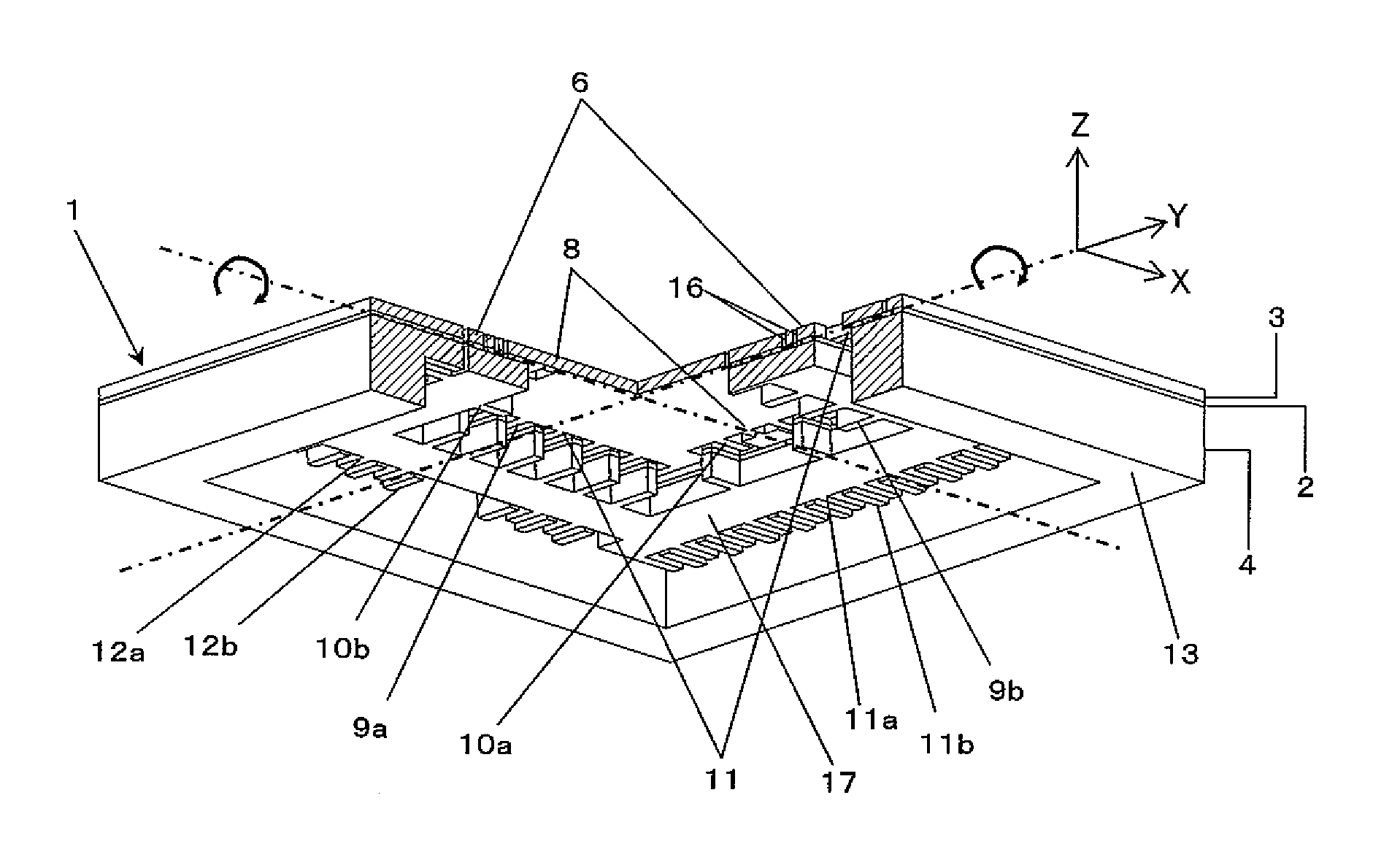
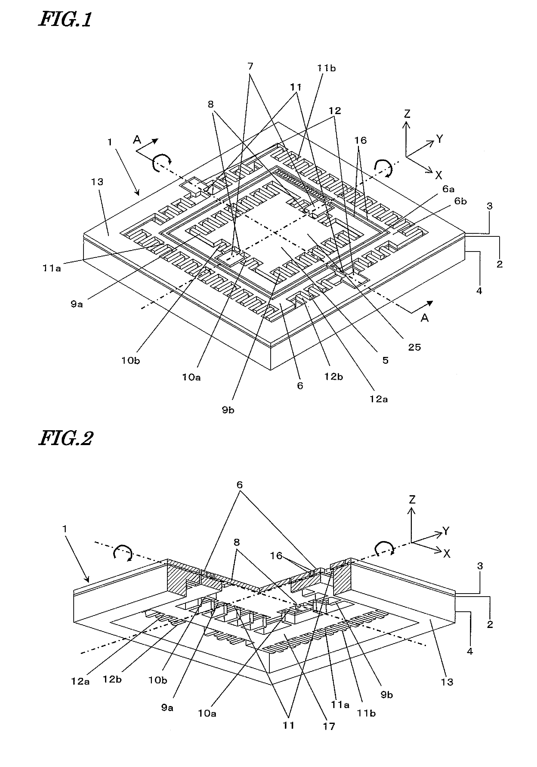
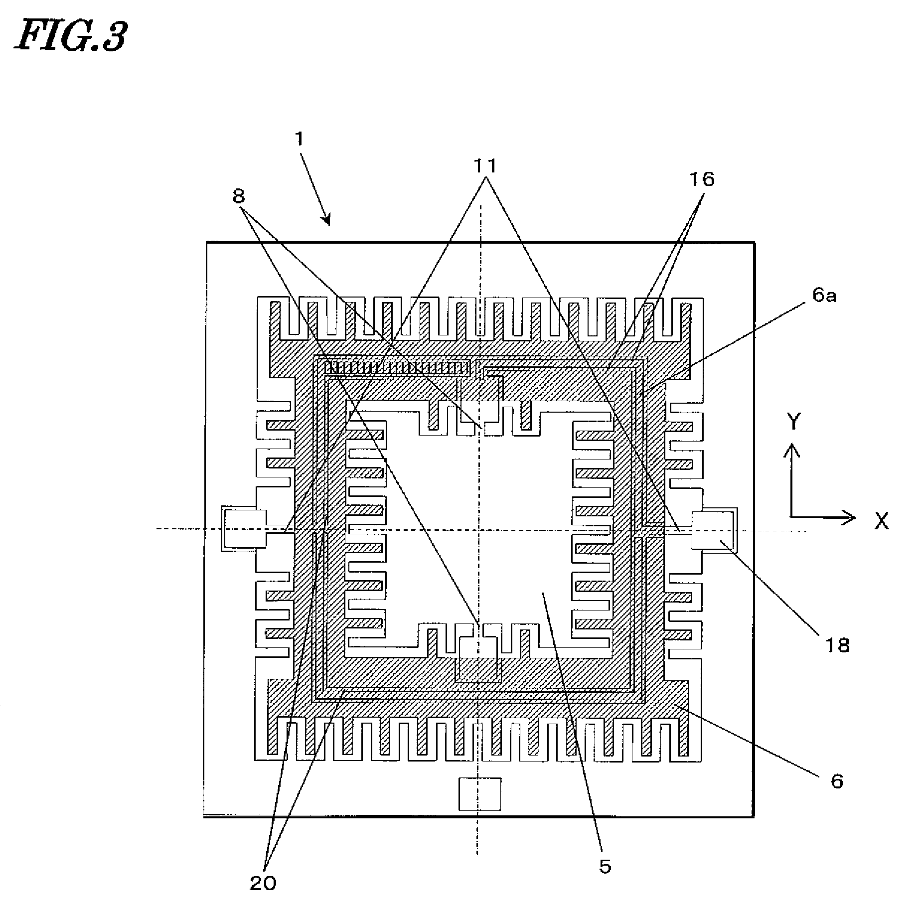
[0130]First, with reference to FIG. 1, an actuator according to a first embodiment of the present invention will be described. FIG. 1 is a perspective view showing a resonant mirror device 1, which is an actuator of the present embodiment.

[0131]The resonant mirror device 1 is produced by processing a wafer in which two silicon layers are bonded via an insulating layer 2 of silicon oxide (SiO2), i.e., a so-called SOT (Silicon On Insulator) wafer, for example.

[0132]Among the two silicon layers, a first silicon layer is doped with an n type impurity such as phosphorus (P) or arsenic (As) or a p type impurity such as boron (B) so that an electrical conductivity is conferred thereto, and thus is referred to as a device layer 3. A second silicon layer is a thick portion that constitutes a main portion of the wafer, and is referred to as a handle layer 4.

[0133]By subjecting the device layer 3 to an etching-based patterning described below, a first movable section 5 and a second movable sec...

embodiment 2

[0200]Next, with reference to FIG. 12, an image projection apparatus 100 according to a second embodiment of the present invention will be described. FIG. 12 is a diagram showing an image projection apparatus 100 incorporating the aforementioned resonant mirror device 1.

[0201]The image projection apparatus 100 includes a resonant mirror device 1, light sources 151, collimating lenses 152, a dichroic prism 153, a control section 156, a laser modulation circuit 157, and a driving section 158. The collimating lenses 152 and the dichroic prism 153 are optics for guiding light beams which are emitted from the light sources 151 to the resonant mirror device 1.

[0202]In accordance with an image signal 155 which is input to the image projection apparatus 100, the control section 156 controls the operation of the laser modulation circuit 157 and the driving section 158. The driving section 158 drives the resonant mirror device 1. The laser modulation circuit 157 generates a modulation signal ...


PUM


Abstract

The present invention is directed to a bi-axial pivoting type actuator having a first movable section, a second movable section supporting the first movable section, and backlining. A first conductive portion and a second conductive portion for independently applying a driving voltage to each of the first movable section and the second movable section are provided on the second movable section, in a state of being split by isolation trenches and being stabilized by the backlining provided under the second movable section. By providing such backlining, mutual stabilization of the first conductive portion and the second conductive portion in an electrically isolated state, and simplification of the production steps for the actuator are realized. By providing a mirror on the first conductive portion of the actuator of the present invention as such, it becomes possible to provide a bi-axial pivoting type mirror device through a simple production process.

Description

TECHNICAL FIELD[0001]The present invention relates to an actuator as a micromechanism to which micromachining technology is applied, and may be used for e.g. optical scanning apparatuses for use in laser printers and the like, reading apparatuses such as bar-code readers, laser projectors, and so on.BACKGROUND ART[0002]In an oscillating mirror device which is formed by micromachining technology, a mirror section is supported by two hinges which are provided along the same line, for example. An electrode is provided at a position opposing the mirror section. Due to an electrostatic attraction occurring between the mirror section and the electrode, the mirror section undergoes reciprocating oscillation, with the two hinges acting as twist pivot axes.[0003]As compared to a mirror device in which a polygon mirror is rotated by a motor, such an oscillating mirror device has a simple structure and permits batch processing in a semiconductor process, and thus is easy to be downsized and ha...

Claims


Application Information

Patent Timeline
Patent Type & Authority Patents(United States)
IPC IPC(8): G02B26/08H02N1/00
CPCB81B3/007G02B26/0841H02N1/006B81B2201/033B81B2201/042B81B2203/0136H04N2201/0082B81B2207/07H04N1/113B81B2203/058
Inventor OBI, HIROSHITOMITA, HIRONORIKUROZUKA, AKIRA
Owner PANASONIC CORP
Why Eureka
Try Eureka