
Magnetic resonance based apparatus and method to analyze and to measure the bi-directional flow regime in a transport or a production conduit of complex fluids, in real time and real flow-rate

a technology of complex fluids and magnetic resonance, applied in the direction of nuclear magnetic resonance analysis, reradiation, instruments, etc., can solve the problems of difficult technology implementation, too fast, and little practical and expensive implementation,

Active Publication Date: 2011-01-18
SIEP +1
View PDF16 Cites 43 Cited by
  • Summary
  • Abstract
  • Description
  • Claims
  • Application Information

AI Technical Summary

Benefits of technology

The invention is a method and device for non-invasive and non-destructive measurement of the flow rate and proportions of different components in a complex fluid in real-time and flow. This can be applied to various fields such as the oil industry, dairy industry, and food and extruded organic materials. The method uses magnetic resonance based analysis and a control computer for acquisition and data transfer. The device includes two magnetic prepolarization modules of variable effective length and a homogeneous, thermally compensated, and constant magnetic field. The method allows for the analysis and measurement of bi-directional flow regimes in a transport or production pipe of complex fluids.

Problems solved by technology

Those are little practical and expensive to be implemented, as well as of difficult application in petroleum fields with rigorous climatic conditions generally.
This method has the disadvantage that, at the speeds at which the protons commonly move in the magnetic field when the fluid flow-rate is measured under reservoir conditions, is too fast.
Therefore, the application of fast rise time magnetic field gradients switching on and off is of difficult technological implementation.
This means that this methodology is generally restricted to measurements at relatively low flow-rates.
Therefore, the MR signal to noise ratio deteriorates.

Method used


Image

  • Magnetic resonance based apparatus and method to analyze and to measure the bi-directional flow regime in a transport or a production conduit of complex fluids, in real time and real flow-rate
  • Magnetic resonance based apparatus and method to analyze and to measure the bi-directional flow regime in a transport or a production conduit of complex fluids, in real time and real flow-rate
  • Magnetic resonance based apparatus and method to analyze and to measure the bi-directional flow regime in a transport or a production conduit of complex fluids, in real time and real flow-rate

Examples


Embodiment Construction

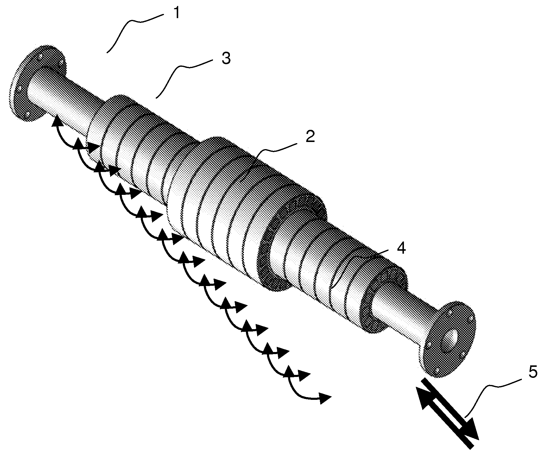
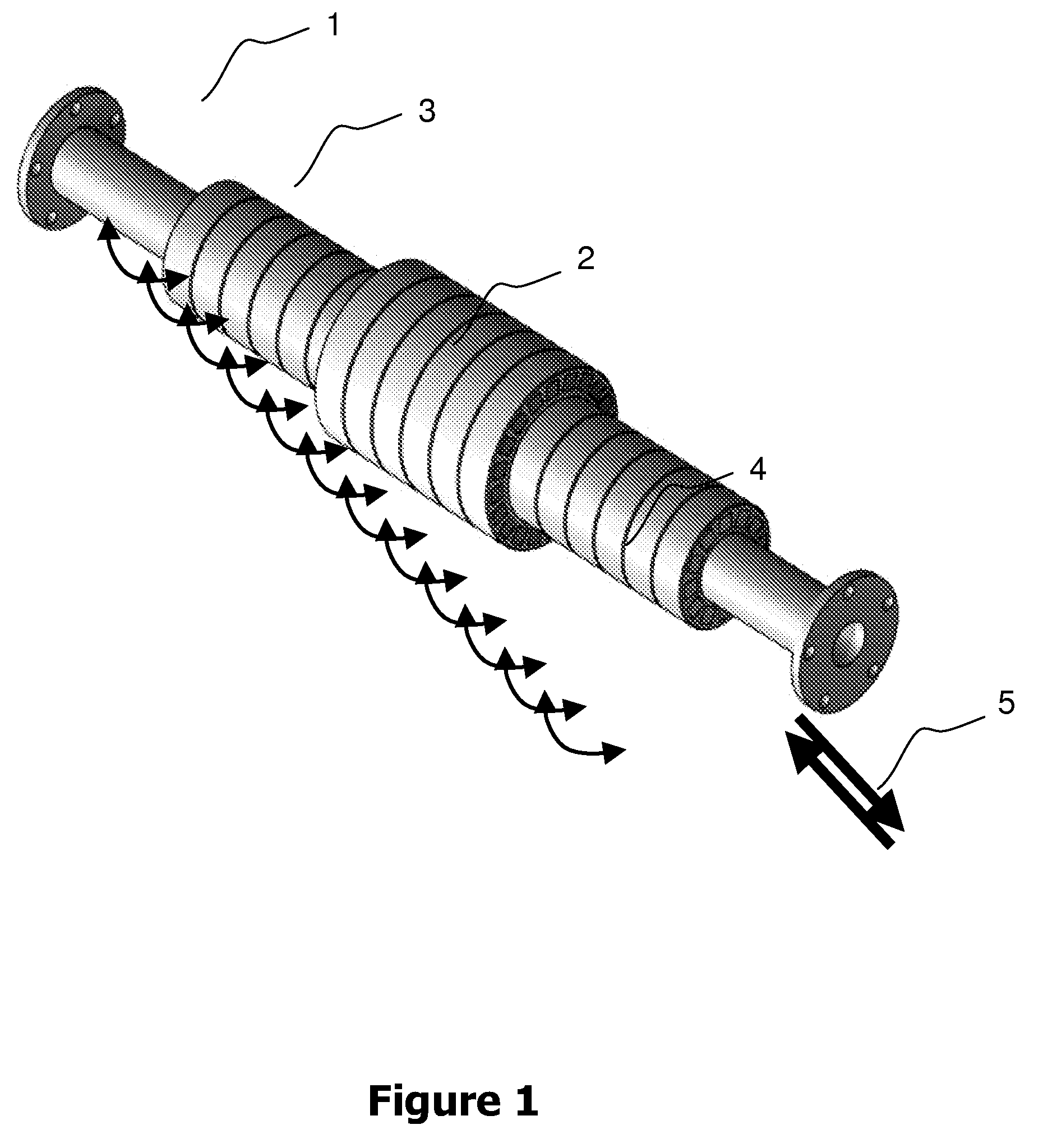
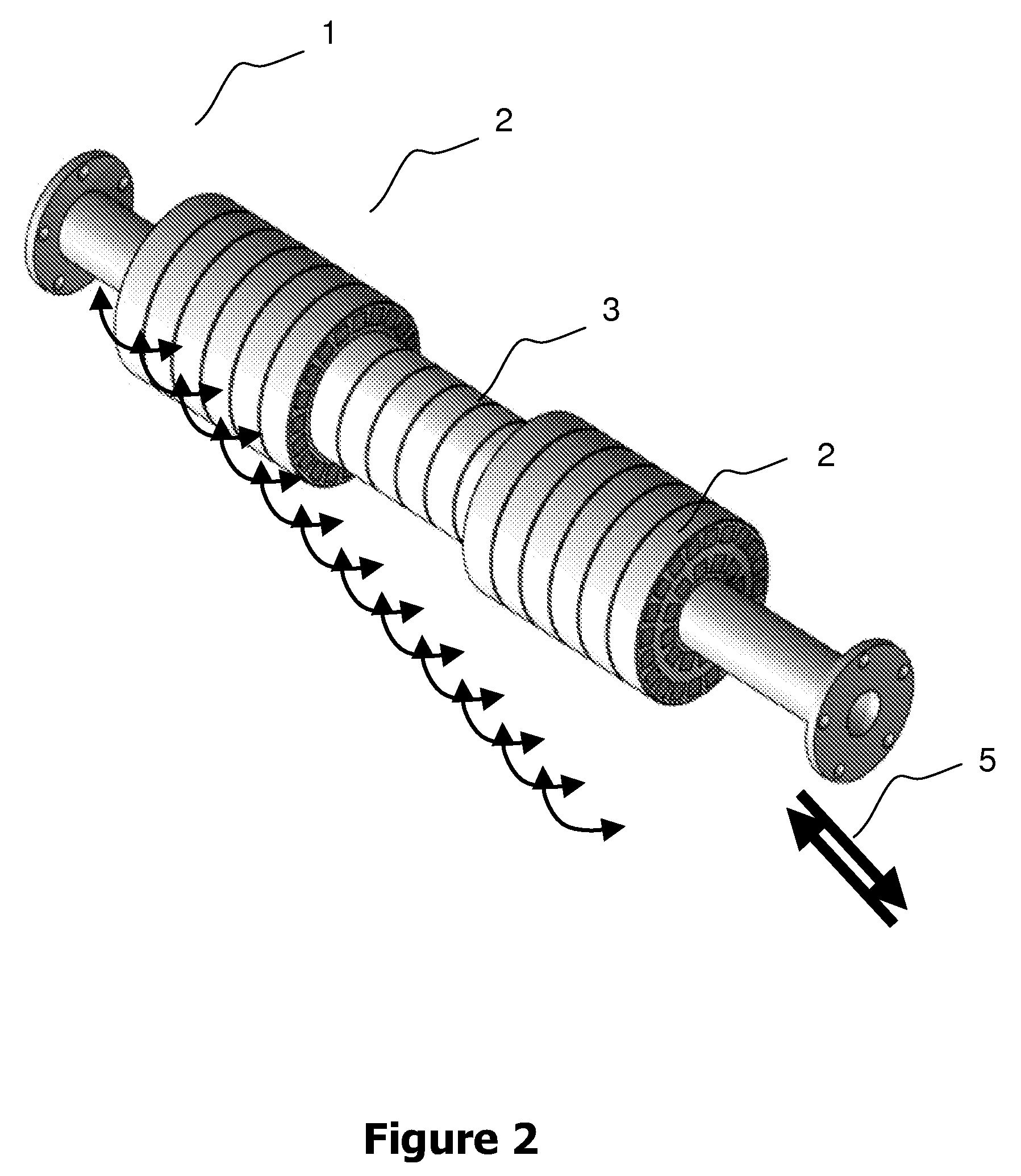
[0039]FIG. 1 shows a simplified block chart of the preferred embodiment of this invention. The complex fluid flows through the production vein 1 in any of the two possible directions; a phase can also flow in one direction and the other / others in the opposite one 5. If the flow of the phase, whose regime needs to be measured or characterized, flows from the left to the right, for example, it comes first into the prepolarization magnet of effective variable length to polarize the spins of the phases that come from the left 3; then the fluid comes into the measurement and characterization set of the velocity profile 2. The following step 4 produces no effects in this situation, as it is adjusted to an effective zero polarization length. The magnetic field generated in the first step 3 allows choosing the phase of the fluid to be measured in the following step 2. This operation is made by the relation between the average velocity of such phase in the pipe, the value of the relaxation t...


PUM


Abstract

An apparatus and a method is provided based on the Magnetic Resonance techniques to analyze and measure a uni- and / or a bi-directional flow regime of multiphase fluids in a transport and production conduct, in real time and flow-rates, based on a magnetic resonance analytical module, two magnetic prepolarization modules of variable effective length and a control computer of data acquisition and transfer, all associated to each other.

Description

FIELD OF THE INVENTION[0001]The present invention is related to the direct determination in the production line, of the flow regime in a multiphase complex fluid, by the selective measurement by Magnetic Resonance (MR) of the velocity profile of each separate phase, in a transversal slice to the flow direction. The present invention is specifically related to a method and an apparatus to measure, in real time and real production volumes, the individual component flow-rates, the relative proportions of the different phases that compose the complex fluid and the spatial profile of velocities in the fluid vein, in both uni and bidirectional flowing fluids. In particular, the present invention is applied preferably to the analysis of the flow in oil industry production veins, as well as in other conducts that transport diverse types of fluids, including, for example, the cases where water and petroleum move in opposite directions. The analysis is performed on a non-invasive and non-dest...

Claims


Application Information

Patent Timeline
Patent Type & Authority Patents(United States)
IPC IPC(8): G01V3/00
CPCG01F1/56G01F1/58G01F1/716G01F1/74G01N24/08G01R33/383G01R33/5617G01R33/56308G01N24/081G01N24/085
Inventor PUSIOL, DANIELCARPINELLA, MARIELAALBERT, GABRIELAOSAN, TRISTANOLLE, JUAN MANUELFREEMAN, JOHN JUSTINAPPEL, MATTHIASESPEJO, IRENE SILVINA LOPEZ GAMUNDI
Owner SIEP
Learn More