Free standing modular display

a modular display and freestanding technology, applied in the direction of dismountable cabinets, identification means, ways, etc., can solve the problems of occupying valuable booth space, high cost, transportation, set-up, storage, etc., and achieve the effect of avoiding wrinkles

Inactive Publication Date: 2011-01-25
FLAGG RODGER H
View PDF24 Cites 54 Cited by
  • Summary
  • Abstract
  • Description
  • Claims
  • Application Information

AI Technical Summary

Benefits of technology

[0011]Therefore, one object of this invention is to provide a new and improved free standing modular display assembly for tradeshows and events, with at least two upright sub-assemblies which are each vertically extendable for display, and retractable for ease of transport and storage.
[0013]Another object of this invention is to secure a first set of flexibly biased, resilient spacer material near the upper end of the inner surface of the outer tubular member, and a second set of flexibly biased, resilient spacer material secured near the lower end of the outer surface of the inner tubular member, to provide a slidable, resilient, in-line slip fit between the inner and outer tubular members, enabling the inner and outer tubular members to selectively extend substantially vertically in-line for use, and to retract in-line for ease of transport or storage, using standard, commercially available tubing sizes, thereby saving the extra cost for custom slip-fit tubing.
[0015]Another object of this invention is to tension the flexible sheet material at the upper end of each of the inner tubular members to avoid wrinkles caused by compression, expansion or temperature change, when the free standing modular display assembly is releasably secured in the extended position to one or more sets of first and second horizontal bars.
[0016]Still another object of this invention is to releasably secure the second horizontal bar to the respective third or fourth radial positioning members on adjacent upright sub-assemblies; while the adjacent, upright sub-assemblies are in an initial retracted position, and then to selectively raise the inner tubular member of each upright sub-assembly to a fully extended position for display; and to selectively lower the inner tubular member on adjacent upright sub-assemblies from the extended position to the retracted position, for ease of removal of the second horizontal bar from the third or fourth radial positioning members on adjacent upright sub-assemblies, without the need for tools or a ladder.

Problems solved by technology

Tradeshows and events offer limited booth space to individuals and large and small businesses for a fee.
Pop up floor displays are popular, but they take up valuable booth space, and are expensive.
Rigid backdrops require large containers to ship, which are expensive to transport, set-up, and store between use.

Method used


Image

  • Free standing modular display
  • Free standing modular display
  • Free standing modular display

Examples


Embodiment Construction

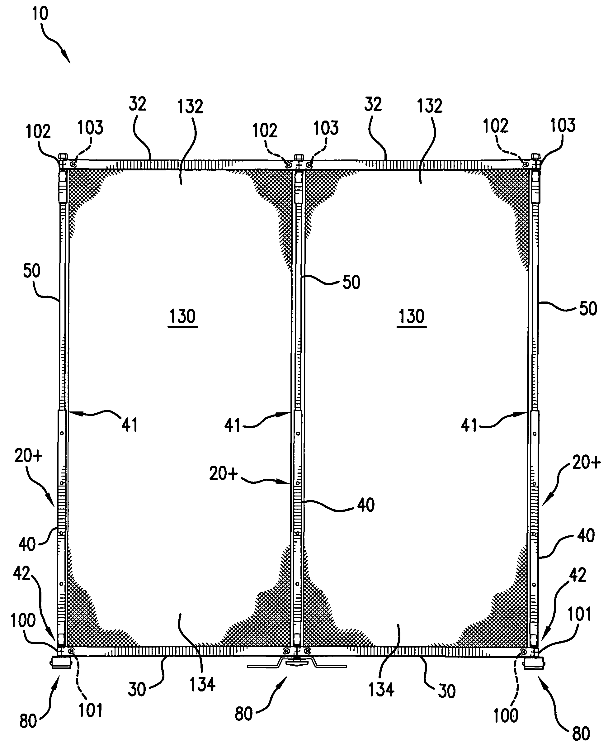
[0039]As shown in FIG. 2A, the free standing modular display assembly 10, comprises at least two upright sub-assemblies 20+ spaced apart and joined by a set of first and second horizontal bars 30, 32.

[0040]Each set of first and second horizontal bars 30, 32 preferably has a rectangular cross-section having a narrow width, and a height at least six to twelve times its width. The first horizontal bar 30 may be positioned and releasably secured in a horizontal in-line position, or may be radially, horizontally bowed between adjacent upright sub-assemblies 20+ in one of a convex 114 or concave 116 position, or alternately arranged in a right-angle 120 configuration.

[0041]One of the opposing end portions 31 of a first horizontal bar 30 is releasably secured to one of the arms 115, 117 extending from the respective first and second radial positioning members 100, 101 on the first upright sub-assembly 20+, and the opposite end portion 33 of the first horizontal bar 30 is releasably secured...


PUM


Abstract

At least two upright subassemblies, each with a base, radial positioning members; an outer tubular member, an inner tubular member slidably received in the outer tubular member; a plunger for selective engagement with aperture(s) in the outer tubular member, upper and lower horizontal bars secured to the radial positioning members, and a flexible display secured to each set of upper and lower horizontal bars, the radial positioning members for selective positioning between selected convex, concave, in-line and right angle positions.

Description

CROSS-REFERENCE TO RELATED TOPICS[0001]This disclosure claims priority of provisional patent application 61 / 213,152 filed May 12, 2009, entitled: FREE STANDING MODULAR DISPLAY, which is incorporated in full by reference herein.STATEMENT REGARDING FEDERALLY SPONSORED RESEARCH OR DEVELOPMENT[0002]Not applicableREFERENCE TO SEQUENCE LISTING A TABLE, OR A COMPUTER PROGRAM LISTING COMPACT DISK APPENDIX[0003]Not applicable[0004]For purposes of this disclosure, the term “releasably secured” is intended to convey a fastening means which may be selectively, manually secured or released by a user's hand, without the need for hand tools or power tools.BACKGROUND OF THE INVENTION[0005]Tradeshows and events offer limited booth space to individuals and large and small businesses for a fee. Often a tradeshow lasts several days, and the user selects booth space in accordance with their budget and their display needs. Some booth space is as small as a six foot table. Usually, booth space is rented i...

Claims


Application Information

Patent Timeline
Patent Type & Authority Patents(United States)
IPC IPC(8): G09F7/00E06B9/24E06B9/00G09F15/00G09F15/02G09F3/20A47G5/00
CPCG09F15/0068
Inventor FLAGG, RODGER H.
Owner FLAGG RODGER H
Why Eureka
Try Eureka