Two-speed PTO stub shaft exchange improvements

a stub shaft and two-speed technology, applied in the direction of interengaging clutches, couplings, gearing, etc., can solve the problems of tedious installation and time-consuming, and achieve the effect of improving the installation and removal process and enhancing the design of the stub sha

Inactive Publication Date: 2011-01-25
DEERE & CO
View PDF9 Cites 8 Cited by
  • Summary
  • Abstract
  • Description
  • Claims
  • Application Information

AI Technical Summary

Benefits of technology

[0006]In view of the above, and in accordance with one aspect of the present invention, one object of the invention is to improve the installation and removal process of the two speed reversible PTO stub shaft by enhancing the stub shaft design to enable the operator to easily insert the stub shaft into the output shaft against a spring loaded mechanism by twisting the shaft to align the gear collar teeth to the appropriate gear.
[0007]Another object of this invention is to quickly and easily install or remove the power take-off shaft by providing a recess on the front interior top end portion of the output shaft to capture or contain the snap ring which is fastened around the PTO stub shaft. This allows the installer to let go of the tool used to squeeze the snap ring and use both hands to insert the stub shaft against the collar return spring and twist the shaft to align the collar teeth to the gear.

Problems solved by technology

One disadvantage of a PTO shaft and current flanged locking mechanisms is that it tends to be tedious and time consuming to install, which may require the use of an additional person or an additional hand.

Method used


Image

  • Two-speed PTO stub shaft exchange improvements
  • Two-speed PTO stub shaft exchange improvements
  • Two-speed PTO stub shaft exchange improvements

Examples


Embodiment Construction

[0015]While the present invention is susceptible of embodiments in various forms, there is shown in the drawings and will hereinafter be described a preferred embodiment of the invention with the understanding that the present disclosure is to be considered as setting forth an exemplification of the invention which is not intended to limit the invention to the specific embodiment illustrated.

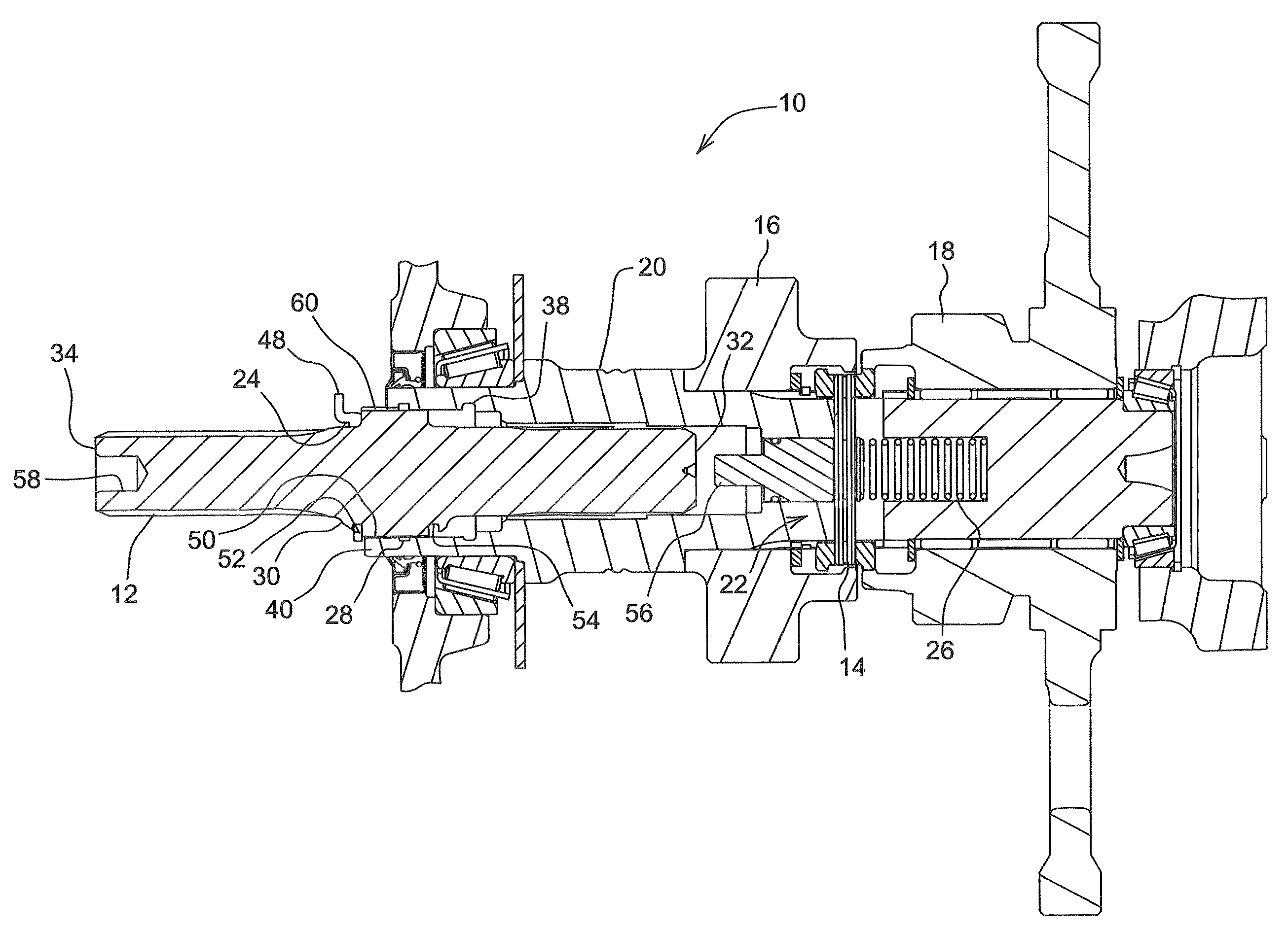
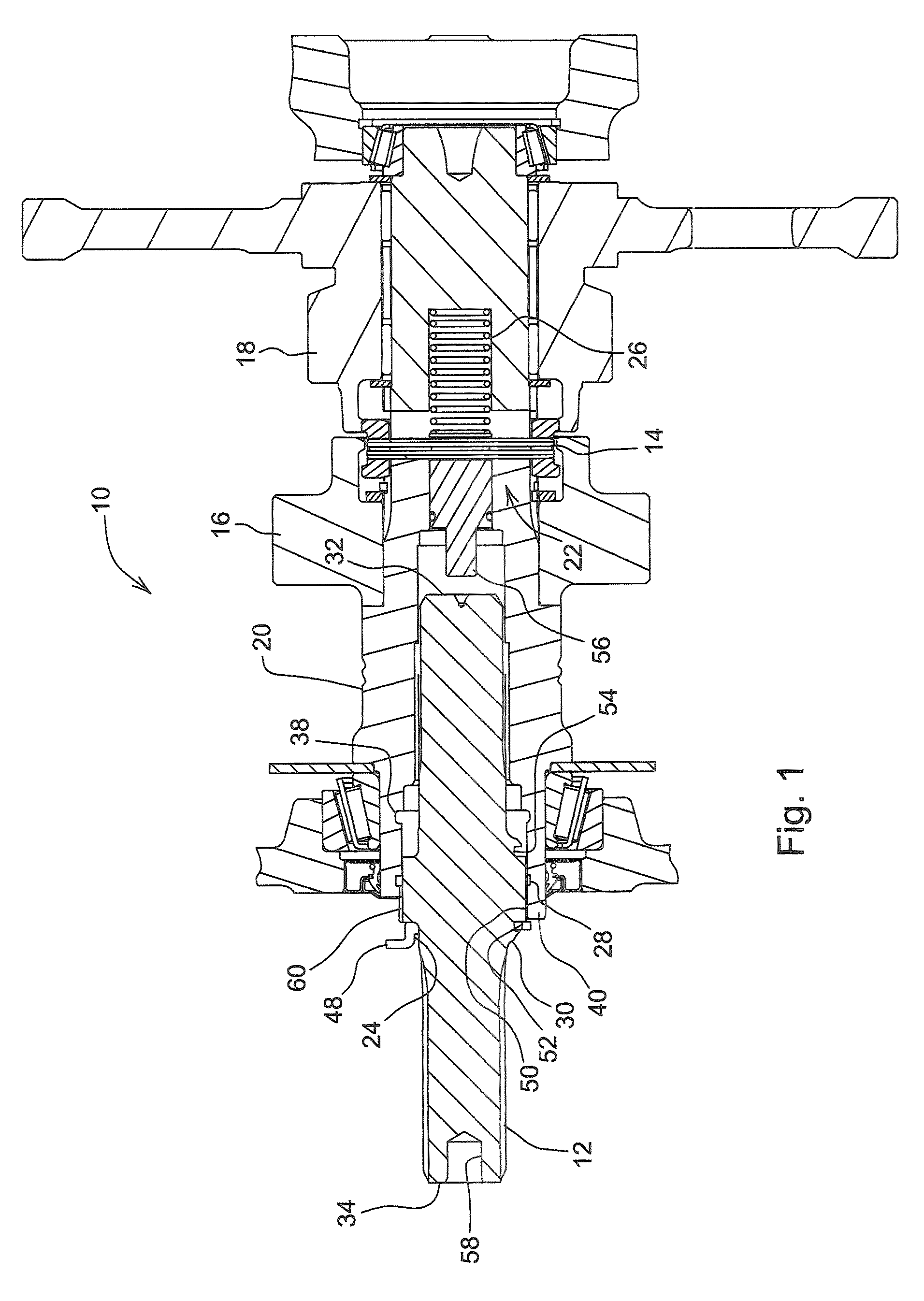
[0016]Referring now to the drawings, wherein like reference numerals refer to like parts throughout the several views, there is shown in FIG. 1 a PTO assembly 10. A gear collar 14 is located between a first gear 16 and a second gear 18 and is capable of sliding axially between a first speed and a second speed, respectively 1000 rpm and 540 rpm.

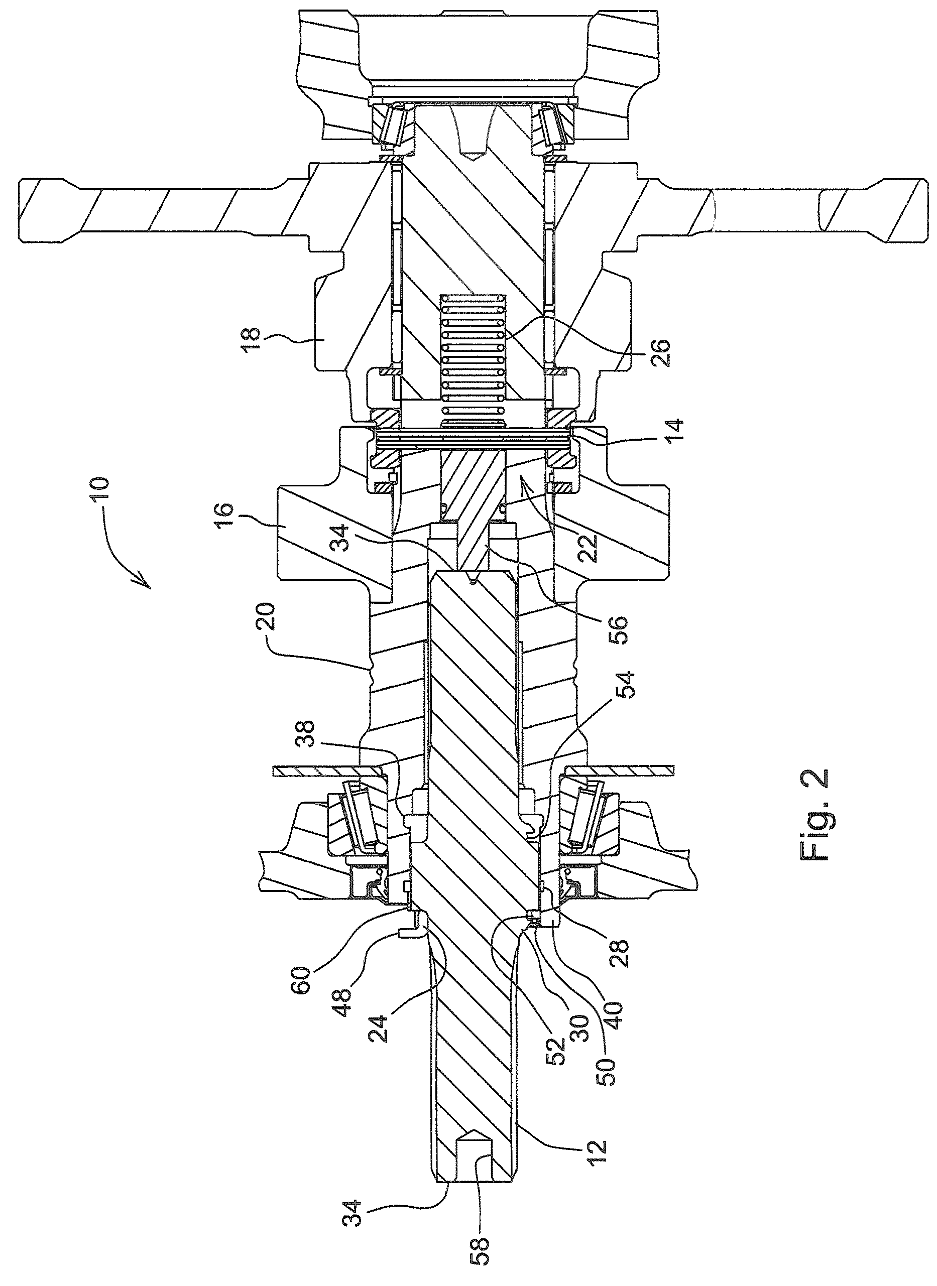
[0017]FIGS. 1-3 show a snap ring 24 fastened around the outer surface of a PTO stub shaft 12. A PTO output shaft 20 has an internal spline 38 and an installation surface 50. The PTO stub shaft 12 has a first recess 52 and an external spline 60, wherein the...


PUM


Abstract

A power take-off assembly for a work vehicle including an improved power take-off shaft for installation and removal. The power take off shaft is extended and a cut out section on the first end of the shaft is provided to engage an extended portion of a spring loaded mechanism. Once the cut out section securely fits over the extended portion, the spring loaded mechanism is prevented from axially moving in a rightward direction, thus enabling the spring to hold the gear collar in place to engage the high speed gear. The PTO stub shaft has an extended end with protruding shoulders which serve to capture the snap ring between the stub shaft and the output shaft so that when the stub is moved axially the shoulders will pull the snap ring into the groove on the output shaft which securely fastens the stub shaft. A cut-out section on the front end surface of the output shaft is also provided to allow clearance for the tool to squeeze the snap ring tabs during installation and removal.

Description

FIELD OF THE INVENTION[0001]The present invention relates generally to a reversible two speed PTO Stub Shaft, and more specifically to an improved PTO Stub Shaft for a cheaper and efficient installation process.BACKGROUND OF THE INVENTION[0002]Power Take-Off Shafts or PTOs are used on agricultural vehicles such as tractors to provide power from the engine to agricultural implements. As the use of PTOs developed over the years, the industry developed a standard for two speed PTOs comprising gear speeds of 1000 and 540 rpms. Thus in order to accommodate industry standards of a particular implement relative to the appropriate gear speed, it is necessary to provide a power take-off assembly which allows quick and easy installation of a proper PTO assemblies, the output shaft has a internally splined portion adapted to axially receive the externally splined reversible power take off shaft to prevent relative rotational movement between the power take-off stub shaft and output shaft. The ...

Claims


Application Information

Patent Timeline
Patent Type & Authority Patents(United States)
IPC IPC(8): F16H37/00
CPCB60K17/28F16D2001/103F16D1/116F16B21/183F16D2011/004F16D21/04
Inventor STEELE, DAVID M.WEIHS, JOHN A.SCHOTT, ALLAN N.FOX, DANIEL J.LARSON, WADE T.
Owner DEERE & CO
Why Eureka
Try Eureka