Striking tool

a technology of striking tool and hammer, which is applied in the field of hand tools, can solve the problems of reducing weight, reducing material damage, or even injury, and often disadvantageous weight, so as to reduce vibration, reduce damage, and prevent vibration transmission

Active Publication Date: 2011-01-25
POOLE HLDG
View PDF9 Cites 41 Cited by
  • Summary
  • Abstract
  • Description
  • Claims
  • Application Information

AI Technical Summary

Benefits of technology

[0009]More specifically, the exemplary striking tool includes a generally extended handle portion, such as in the form of an I-beam, and a striking head integrally carried at a first end of the handle portion. The handle portion preferably includes a generally broad, flat forward surface adapted to reduce damage caused by overstrikes, i.e. poorly aimed strikes where an impact force is borne by the handle portion. A medial section of the handle portion, however, is generally thin compared to the broad forward surface. A broad rearward surface is preferably also included for stability and strength of the handle portion. The handle portion preferably additionally includes a comfortable grip operable therewith to provide a comfortable and secure gripping surface by which a user may grasp the striking tool.
[0010]The striking head preferably includes a transverse cavity extending therethrough, and a plurality of voids formed therein. The cavity preferably defines an upper beam portion and a lower beam portion. The beam portions preferably reduce vibrations caused by strikes, and substantially prevent transmission of vibrations to the handle portion, while allowing beneficial force transference from mass located on an opposite side of the cavity from the striking surface. More specifically, the striking face is preferably provided on a forward surface of the head, and the beam portions, particularly the upper beam portion, are arranged to substantially prevent compression along an axis of the head extending from the striking face to a rear portion of the head. The nail-pulling tool is preferably disposed proximate the rear portion of the head, as is conventional. The beam portions, particularly the lower beam portion, are arranged to substantially prevent bending between the nail-pulling tool and the handle portion.
[0011]Accordingly, one feature and advantage of the tool of the present disclosure is its ability to provide a strong, yet lightweight handle portion having a broad flat forward surface adapted to reduce damage caused by overstrikes.
[0012]Another feature and advantage of the tool of the present disclosure is its ability to provide a durable striking tool capable of delivering great impact forces while providing a beneficial weight distribution and balance for ease of use.

Problems solved by technology

While such tools exhibit acceptable durability characteristics, they are frequently disadvantageously heavy.
As a result, a user may become strained or fatigued from use, resulting in poor control of strikes, damage to materials, or even injury.
Reduction of weight, however, affects a striking force delivered to the selected target when struck at a given velocity.
Since certain tasks require substantial striking forces, reducing the weight of a striking tool is not always possible or beneficial.
Additionally, and particularly when used to deliver large force strikes, striking tools may disadvantageously transmit impact vibrations to a user through the handle.
Such vibrations can accelerate the onset of strain or fatigue, and cause the user to experience discomfort.
Furthermore, such vibrations can contribute to material strain and fatigue, causing damage to the tool itself, reducing tool life and posing a threat of injury.
Such cushioned handles, however, fail to prevent vibrations within the tool, and merely serve to isolate a user's hand for comfort.

Method used


Image

  • Striking tool
  • Striking tool
  • Striking tool

Examples


Embodiment Construction

[0022]In describing exemplary embodiments of the hammer of the present disclosure illustrated in the drawings, specific terminology is employed for the sake of clarity. The claimed invention, however, is not intended to be limited to the specific terminology so selected, and it is to be understood that each specific element includes all technical equivalents that operate in a similar manner to accomplish a similar purpose.

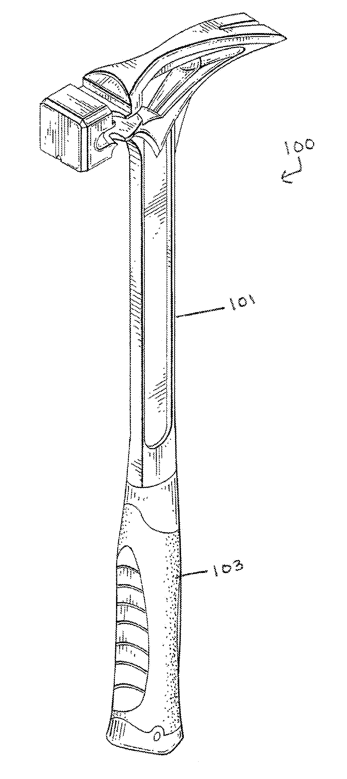
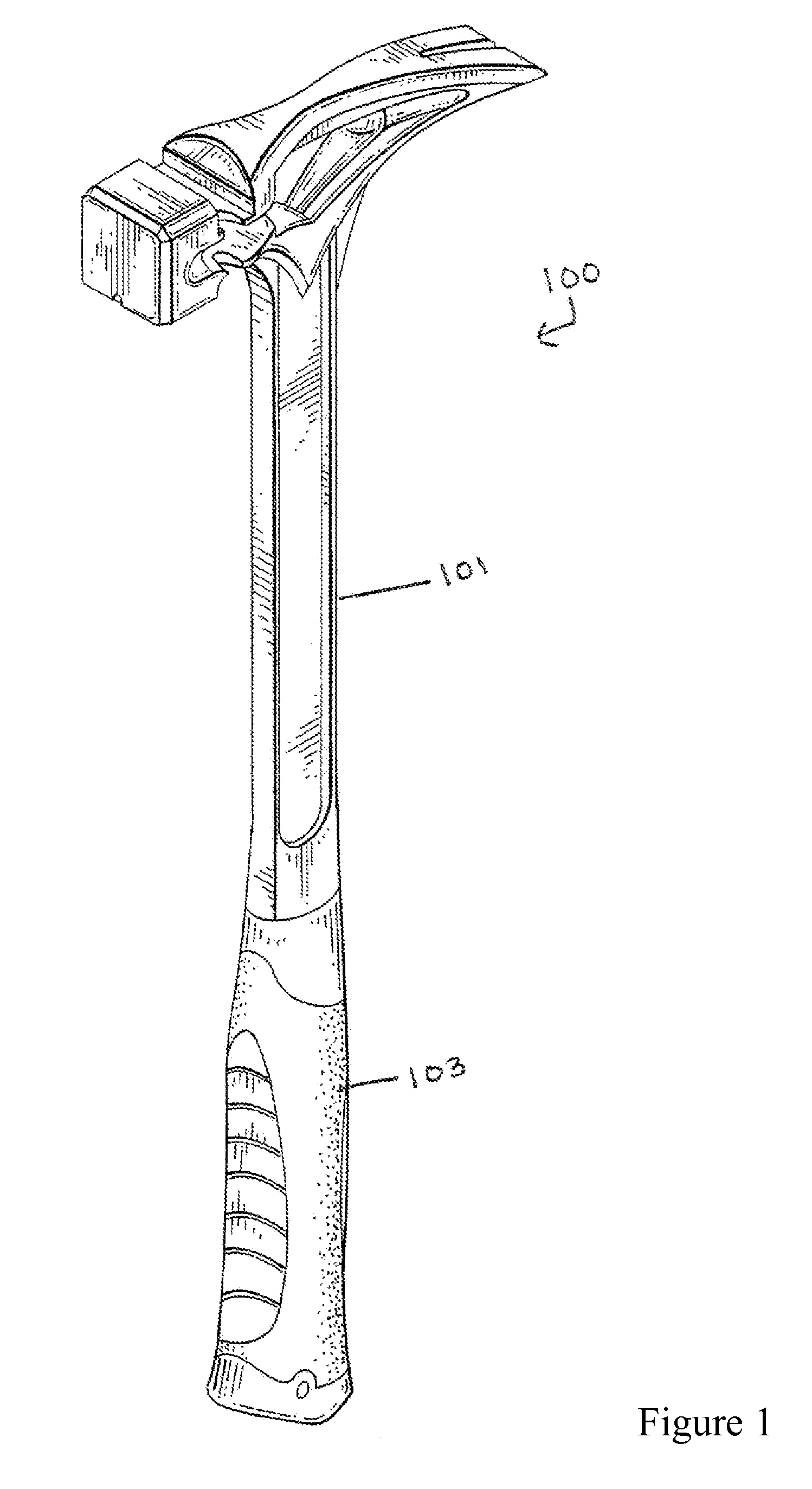
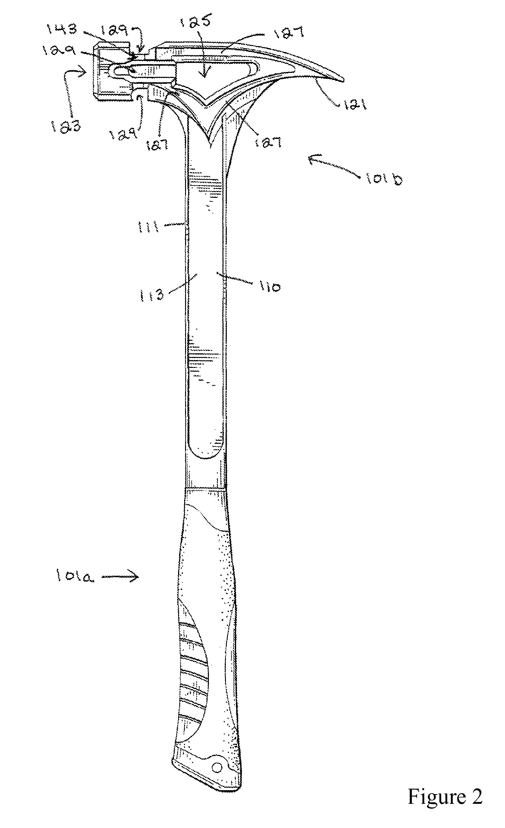
[0023]In that form of the hammer of the present disclosure chosen for purposes of illustration, FIGS. 1-6 show hammer 100 including body 101 and grip 103. Body 101 is preferably formed as a monolithic or unitary member from a suitable metal, composite, or synthetic material, or the like, defining handle 110 and head 120, and includes grip 103 formed or installed thereon. Body 101 is preferably formed from steel. Grip 103 may be formed from natural or synthetic rubber, plastic, composite, or the like, and may be resilient and / or sculptured or contoured to provide a ...


PUM


Abstract

A hammer that that reduces vibration and provides advantageous balance and mass distribution having a handle portion comprising an I-shape sectional profile and a head comprising a cavity formed therethrough. The hammer may further comprise various nail or other fastener removal structures, such as a claw, slots, notches, or the like. The hammer may further include a nail-starter with magnetic nail retention.

Description

CROSS REFERENCE TO RELATED APPLICATIONS[0001]This application claims the benefit of U.S. application Ser. No. 12 / 387,761 filed on May 6, 2009 currently pending the contents of which is hereby incorporated by reference, which in turn claimed priority to U.S. Provisional Application Ser. No. 61 / 050,963 filed on May 6, 2008, the contents of which is hereby incorporated by reference.TECHNICAL FIELD[0002]The present disclosure relates generally to hand tools, and, more particularly, to a striking tool, such as a hammer, or the like.BACKGROUND OF THE INVENTION[0003]For many different purposes, striking tools, such as hammers, or the like, have been employed for delivering or imparting an impact force to a selected target. Forces generated by even light-duty striking tools can be considerable due to the mechanical advantage involved with such tools. Accordingly, striking tools have been developed having durable, sometimes hardened materials, at least in a striking head or striking surface ...

Claims


Application Information

Patent Timeline
Patent Type & Authority Patents(United States)
IPC IPC(8): B25D1/12B25D1/00
CPCB25D1/06B25D1/12
Inventor HANLON, JARED
Owner POOLE HLDG
Why Eureka
Try Eureka