Purge gas unit and purge gas supply integrated unit

a technology of purge gas and integrated unit, which is applied in the direction of valve housing, transportation and packaging, and well accessories. it can solve the problems of large foot space, poor yielding percentage, and remarkably problematic foot spa

Inactive Publication Date: 2011-01-25
CKD +1
View PDF16 Cites 7 Cited by
  • Summary
  • Abstract
  • Description
  • Claims
  • Application Information

AI Technical Summary

Benefits of technology

[0008]The present invention has been made in view of the above circumstances and has an object to provide a purge gas unit and a purge gas supply integrated unit having a smaller foot space.
[0009]To achieve the purpose of the invention, there is provided a purge gas unit comprising: an input block for input of purge gas into the purge gas unit, the input block including a purge passage formed through the input block to provide an opening in a side surface of the input block and an input passage formed branching off from the purge passage; an output block for output of the purge gas from the purge gas unit; and a communication block connected to the input block and the output block to provide communication between the input block and the output block.

Problems solved by technology

In this case, if process gas remains in the process gas unit, compositions of the process gas are liable to degenerate before being supplied to the chamber, resulting in a poor yielding percentage.
This configuration needs a large foot space (installation space).
As the number of arranged gas lines is increased, the foot space would be remarkably problematic.

Method used


Image

  • Purge gas unit and purge gas supply integrated unit
  • Purge gas unit and purge gas supply integrated unit
  • Purge gas unit and purge gas supply integrated unit

Examples


Embodiment Construction

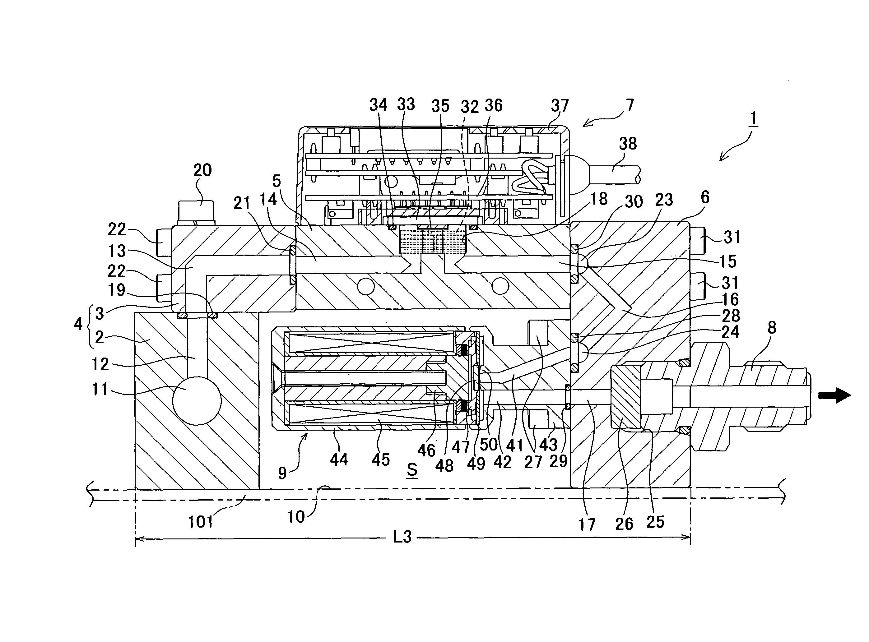
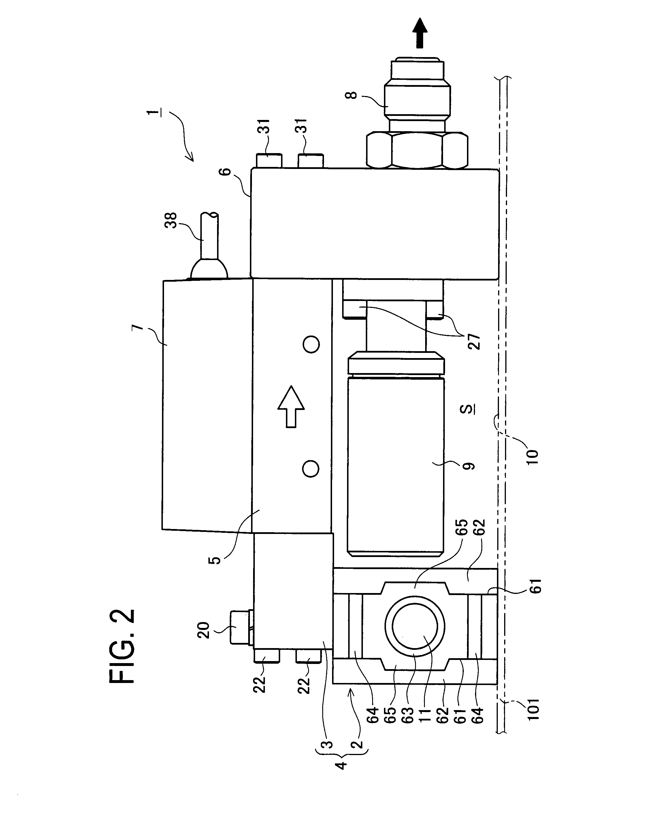
[0025]A detailed description of a preferred embodiment of a purge gas unit and a purge gas supply integrated unit embodying the present invention will now be given referring to the accompanying drawings.

[0026]

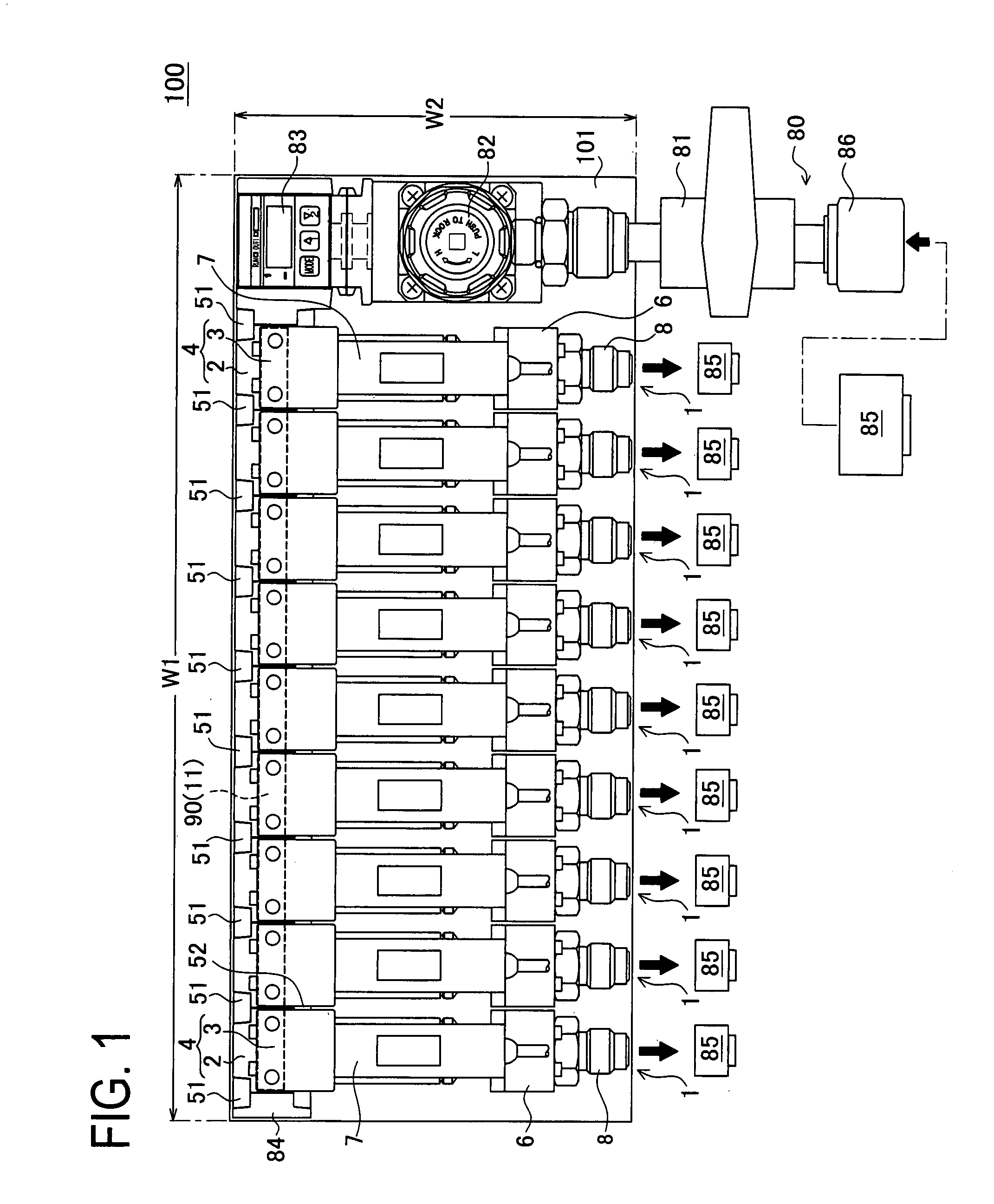
[0027]FIG. 1 is a plan view of a purge gas supply integrated unit 100.

[0028]This purge gas supply integrated unit 100 is mounted in a semiconductor manufacturing system in the same way as the conventional technique. The semiconductor manufacturing system not shown comprises a plurality of process gas units for supplying various kinds of process gasses to a chamber by selecting or mixing the process gasses. The purge gas supply integrated unit 100 of the present embodiment includes purge gas units 1 of the same number (nine in the present embodiment) as process gas units are mounted and integrated on a mounting plate 101 as well as a purge gas supply control unit 80 to supply purge gas in predetermined amounts to a process gas unit not shown.

[0029]The purge gas supply control un...


PUM


Abstract

To provide a purge gas unit and a purge gas supply integrated unit having a smaller foot space, the purge gas unit comprises an input block for input of purge gas into the purge gas unit, the input block including a purge passage formed through the input block to provide an opening in a side surface of the input block and an input passage formed branching off from the purge passage; an output block for output of the purge gas from the purge gas unit; a communication block connected to the input block and the output block to provide communication between the input block and the output block.

Description

BACKGROUND OF THE INVENTION[0001]1. Field of the Invention[0002]The present invention relates to a purge gas unit and a purge gas supply integrated unit, which are arranged to measure a flow rate of purge gas to be supplied to a process gas unit by use of a flow sensor and make feedback control on an open / close control valve based on a measurement result.[0003]2. Description of Related Art[0004]For instance, some semiconductor manufacturing processes include continuous processes in a chamber, e.g., a continuous deposition process on substrates and a cleaning process in the chamber, which are executed by selectively allowing a plurality of process gas units connected to the chamber to communicate with it. This technique is disclosed for example in WO 02 / 93053.[0005]In this case, if process gas remains in the process gas unit, compositions of the process gas are liable to degenerate before being supplied to the chamber, resulting in a poor yielding percentage. To avoid such disadvanta...

Claims


Application Information

Patent Timeline
Patent Type & Authority Patents(United States)
IPC IPC(8): F16K11/10
CPCF15B13/0821F16K27/003Y10T137/87885
Inventor OKABE, TSUNEYUKIMORI, YOJIINAGAKI, TAKEYASUGINO, AKIHITO
Owner CKD
Why Eureka
Try Eureka