Vehicle interior parts

a technology for interior parts and vehicles, applied in the direction of vehicular safety arrangments, vehicle components, pedestrian/occupant safety arrangements, etc., can solve problems such as appearance degrade or misalignment of interior components

Inactive Publication Date: 2011-01-25
KASAI KOGYO CO LTD
View PDF12 Cites 3 Cited by
  • Summary
  • Abstract
  • Description
  • Claims
  • Application Information

AI Technical Summary

Benefits of technology

[0011]According to the first aspect of the present invention, the first locking means provided along the rim of the expanding portion restricts the expanding portion from moving or undulating in a turning direction, to thereby impart stability. Further, the second locking means restricts the expanding portion from moving or undulating in a turning radial direction, to thereby stabilize an attachment state of the automotive interior component.
[0013]According to the second aspect of the present invention, the expanding portion is pushed up at the area at which the first locking means are disposed at longer intervals, when the airbag expands and inflates. The first locking means adjacent to the disengaged ones are disengaged one after another, thereby opening the expanding portion. In this manner, such an automotive interior component can be achieved, that the expanding portion is stably cleaved to form an opening at the time of expansion and inflation of the airbag while the quality in appearance and alignment is ensured.
[0015]According to the third aspect, the second locking means are provided in the area at which the first locking means are disposed at longer intervals, thereby ensuring a stable attachment state to the entire expanding portion.
[0017]According to the fourth aspect of the present invention, the second locking means and third locking means for limiting only movement in the turning radial direction are disposed between the first locking means for limiting movement of the expanding portion in a turning direction. In this manner, there is provided an area at which movement in the turning direction is not limited. Thus, turning of the expanding portion begins at this area, thereby facilitating disengagement of the first locking means. Further, disposition of the third locking means in the area adjacent to the end portions of the expanding portion facilitates movement of the end portions in the turning direction, thereby leading to cleavages at the end portions, so that the expanding portion can be stably opened.
[0019]According to the fifth aspect of the present invention, turning of the expanding portion in the expansion direction thereof is not limited in the partial region of the expanding portion, with which the front end portion of the airbag comes into contact at the beginning of expansion of the airbag. Therefore, the airbag which has started inflating and expanding can complete inflation and expansion in a prompt manner by easily deforming the aforementioned partial region with the inflation pressure of the airbag. This enables the airbag to exert force on the expanding portion in the expansion direction thereof. Further, since the expanding portion is easily expanded, the airbag can easily inflate and expand in the original direction of inflation and expansion.
[0021]According to the sixth aspect, the first locking means provided along the rim of the expanding portion stabilize the expanding portion by limiting movement or undulation thereof in the turning direction. Further, the second locking means limit movement in the turning direction, to thereby stabilize an attachment state of the automotive interior component.

Problems solved by technology

However, the conventional art has entailed a problem that provision of the weak portion in the periphery of the expanding portion as part of the interior component causes the interior component to be misaligned or degraded in appearance due to an occurrence of undulation when it is attached to a vehicle body panel.

Method used


Image

  • Vehicle interior parts
  • Vehicle interior parts
  • Vehicle interior parts

Examples


first embodiment

[0056]In order for the first locking means and the second locking means according to the first embodiment to have their own functions, thereby attaining an effect of the invention, the fitting width D1 of the hook 32 (see FIG. 5B) and intervals between the disposed ribs 31 need to be adjusted in accordance with a layout of the vehicle interior and a design of the interior component to which the present invention is applied.

[0057]FIG. 7 is a schematic view of the area in which the ribs 31 are disposed at a longer interval and in which the hook 32 is disposed at the center. Distance D2 between the hook 32 and the rib 31 is set to a design parameter. With the interior component made of hard material, there is a need to reduce the fitting width D1 of the hook 32 and to widen the distance D2 between the hook 32 and the rib 31. Where the present invention is applied to the door trim 1 molded by blending a polycarbonate (PC) resin and an acrylonitrile butadiene styrene (ABS) resin, in a ca...

second embodiment

[0058]FIG. 8A is a schematic view showing third locking means according to another embodiment of the present invention. The third locking means is made up of ribs 31a serving as a third locking piece, and rib receivers 34 serving as a third engagement portion. The ribs 31a are provided at the expanding portion 3. The rib receivers 34 are provided at the waist garnish 21 serving as a fixed portion with which the rim of the expanding portion 3 comes into contact. The rib receivers 34 receive the ribs 31a to lock movement of the expanding portion 3 in the turning radial direction. As shown in FIG. 8A, in a state in which the expanding portion 3 is closed, the rib 31a is in abutment with the distal end of the rib receiver 34 to restrict the expanding portion 3 from moving in the turning radial direction, i.e., to the waist garnish 21. On the other hand, movement of the expanding portion 3 is not limited in the turning direction. Therefore, like the second locking means described above, ...

third embodiment

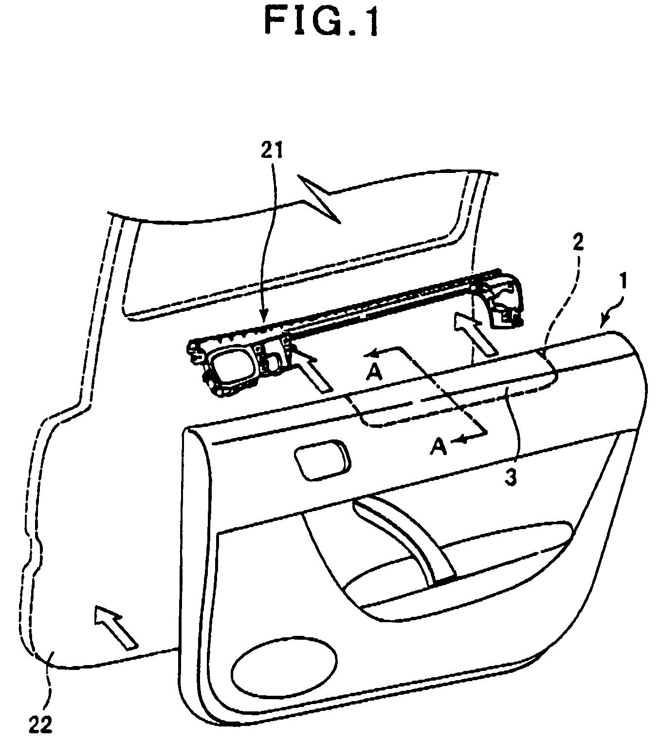
[0060]FIG. 9 is a schematic view of a door trim 101 as viewed from the interior side of the vehicle. The upper portion of the door trim 101 as the interior component is fixed to a vehicle body panel 122 via a waist garnish 121 attached to the vehicle body panel 122.

[0061]The upper side portion of the waist garnish 121 is in abutment with the upper portion rim of the door trim 1, i.e., the so-called waistline, of the door trim 101. As in the first embodiment, the upper side portion is provided, along a part thereof in contact with a rim of an expanding portion 103, with the first engagement portions (rib receivers 134) for receiving the first locking pieces (ribs 131) as the first locking means and second engagement portions (hook receivers 35) for receiving second locking pieces (hooks 132) as the second locking means. In this embodiment, the first locking means is made up of the ribs 131 and the rib receivers 134, whereas the second locking means is made up of the hooks 132 and the...


PUM


Abstract

An automotive interior component according to the present invention includes: an interior component attached to a vehicle body panel at an interior side of a vehicle; an airbag installed in a gap between the vehicle body panel and the interior component; an expanding portion defined in a partial region of the interior component, the expanding portion turning in an expansion direction of the airbag to expose an opening; first locking means made up of a first locking piece provided at a rim of the expanding portion and a first engagement portion provided at a fixed portion with which the rim of the expanding portion comes into contact, receiving the first locking piece to lock movement of the expanding portion in a turning direction; and second locking means made up of a second locking piece provided at the rim of the expanding portion and a second engagement portion provided at the fixed portion with which the rim of the expanding portion comes into contact, receiving the second locking piece to lock movement of the expanding portion in a turning radial direction.

Description

BACKGROUND OF THE INVENTION[0001]1. Field of the Invention[0002]The present invention relates to an automotive interior component incorporating an airbag.[0003]2. Description of the Related Art[0004]An automotive airbag is intended to inflate and expand between a vehicle occupant and a structural body of a vehicle to protect the vehicle occupant from a direct collision with the structural body of the vehicle due to an inertial force at the time of a collision of the vehicle against an obstacle or another vehicle, etc., to thereby ensure safety of the vehicle occupant. Therefore, an airbag device needs to have a function of sensing a collision and reliably completing expansion and inflation of the airbag within a short period of time until the vehicle occupant collides against the vehicle structural body.[0005]Japanese Unexamined Patent Application Publication No. 2006-88731 discloses art directed to an airbag device installed in a side door of the vehicle, in which an airbag can rel...

Claims


Application Information

Patent Timeline
Patent Type & Authority Patents(United States)
IPC IPC(8): B60R21/16B60R21/21B60R21/215B60R21/20
CPCB60R13/0243B60R21/21B60R21/215
Inventor KANEDA, TOSHIHISAAOYAMA, SAORIWATANABE, JIROUTABATA, DAISUKE
Owner KASAI KOGYO CO LTD
Why Eureka
Try Eureka