Electronic apparatus and fuel cell system

a technology of electric equipment and fuel cell, which is applied in the direction of switches, contact mechanisms, instruments, etc., can solve the problem of keeping secondary cells for a long tim

Inactive Publication Date: 2011-01-25
KK TOSHIBA
View PDF15 Cites 1 Cited by
  • Summary
  • Abstract
  • Description
  • Claims
  • Application Information

AI Technical Summary

Benefits of technology

The object of the present invention is to provide an electronic apparatus using a fuel cell as a power supply, which can stop output from the power supply by detecting a non-use state of the electronic apparatus, and a fuel cell system.

Problems solved by technology

However, even in the state in which the electronic apparatus is not used, that is, even in the state in which the load side does not operate at all, fuel is constantly supplied to the fuel cell, and output power is generated from the fuel cell.
Consequently, there arises such a problem that the secondary cell is kept for a long time in a fully charged state or in an approximately fully charged state.

Method used


Image

  • Electronic apparatus and fuel cell system
  • Electronic apparatus and fuel cell system
  • Electronic apparatus and fuel cell system

Examples


first embodiment

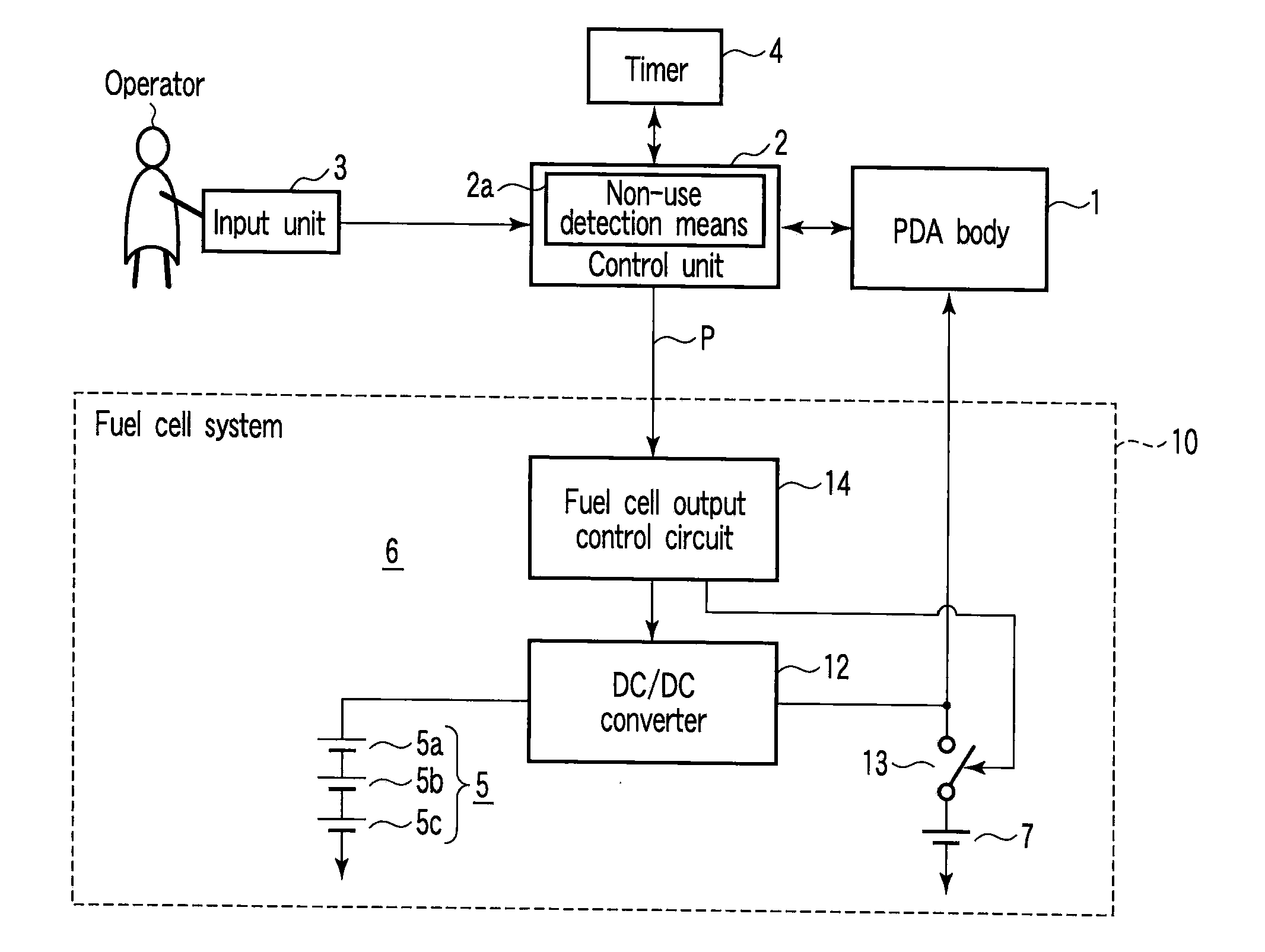
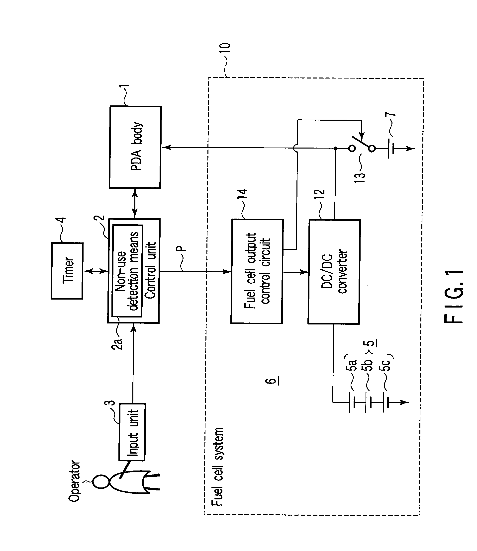
FIG. 1 schematically shows the structure of an electronic apparatus according to a first embodiment of the present invention. FIG. 1 shows a personal digital assistant (PDA) as an example of the electronic apparatus.

In FIG. 1, numeral 1 denotes a PDA body, and a control unit 2 is connected to the PDA 1. An input unit 3 is connected to the control unit 2, and also a timer 4 is connected to the control unit 2.

The control unit 2 controls the PDA 1 in accordance with data which is input from the input unit 3. The control unit 2 controls the functions of the PDA 1, for example, personal information management functions such as schedule management and appointment management. In addition, the control unit 2 controls an electronic dictionary and respective units in the PDA 1 in order to realize a connection function to the Internet. The control unit 2 includes non-use detection means 2a for detecting a non-use state of the PDA 1. The control unit 2 monitors an operation state of the input u...

second embodiment

Next, an electronic apparatus according to a second embodiment of the invention is described.

FIG. 3 schematically shows the electronic apparatus according to the second embodiment of the invention. In the description of FIG. 3, the same parts as those in FIG. 1 are denoted by like reference numerals, and a description is omitted.

In FIG. 3, numeral 21 denotes an electrostatic capacitance sensor, and the electrostatic capacitance sensor 21 includes a pair of electrodes 21a and 21b. The electrodes 21a and 21b are embedded in a sensor mounting unit 22. The sensor mounting unit 22 is disposed on a place where the sensor mounting unit 22 can easily be touched by the operator when the PDA is used, for example, on a part of the PDA case that is held by the operator during operation. In the electrostatic capacitance sensor 21, the electrostatic capacitance between the pair of electrodes 21a and 21b varies in accordance with whether the operator is in touch with the sensor mounting unit 22. A...

third embodiment

Next, an electronic apparatus according to a third embodiment of the invention is described.

FIG. 4 schematically shows the electronic apparatus according to the third embodiment of the invention. In the description of FIG. 4, the same parts as those in FIG. 1 are denoted by like reference numerals, and a description is omitted.

In FIG. 4, numeral 31 denotes an image pickup device functioning as image pickup means. The image pickup device 31 is provided, for example, on the PDA 1 in order to capture images of characteristic parts of the operator, such as the face and body of the operator, when the operator uses the PDA. The control unit 2 is connected to the image pickup device 31 via an A / D converter 32, and a digitally converted image signal is input to the control unit 2. An image memory 33 is connected as memory means to the control unit 2. The image memory 33 stores image data of the characteristic parts of the PDA owner (operator), such as the face and body.

In the control unit 2...


PUM


Abstract

A PDA, which functions as an electronic unit, includes power supply which includes a fuel cell unit and an auxiliary power supply which is charged by an output of the fuel cell unit. A non-use state of the PDA is detected by non-use detection unit. Upon detection of the non-use state by the non-use detection unit, the output from the fuel cell unit is stopped and an output of the auxiliary power supply is shut off.

Description

This application is based upon and claims the benefit of priority from prior Japanese Patent Application No. 2006-087855, filed Mar. 28, 2006, the entire contents of which are incorporated herein by reference.BACKGROUND OF THE INVENTION1. Field of the InventionThe present invention relates to an electronic apparatus in which a fuel cell is used as a power supply, and to a fuel cell system.2. Description of the Related ArtElectronic apparatuses, such as a portable audio device and a personal digital assistant (PDA), have recently been remarkably reduced in size. With the reduction in size of these electronic apparatuses, there has been an attempt to use a fuel cell as a power supply. The fuel cell has the advantage that electricity can be generated simply by supplying a fuel and an oxidizer and electricity can continuously be generated only by replacing the fuel. Thus, if the size of the fuel cell can be reduced, the fuel cell is very effective as a power supply of a small-sized elec...

Claims


Application Information

Patent Timeline
Patent Type & Authority Patents(United States)
IPC IPC(8): H01H9/54
CPCG06F1/26G06F1/3203G06F1/3231G06F1/3246H01M8/04313H01M8/04597H01M8/04656H01M8/0488H01M8/04955H01M16/003H01M8/1011Y02B60/1289Y02E60/50Y02D10/00
Inventor SUZUKI, HIDENORISENOUE, KIYOSHIMIYAHARA, MAKOTOTAKAHASHI, KENICHIKITAMOTO, MICHIYUKIAKAMOTO, YUKINORIOZEKI, YOSHIESHIMOYAMADA, TAKASHIYASUI, HIDEAKIHASEBE, HIROYUKIKAWAMURA, KOICHI
Owner KK TOSHIBA
Why Eureka
Try Eureka